AutoCAD is a software application for 2D and 3D
computer-aided design (CAD) and drafting — available since 1982 as a desktop
application and since 2010 as a mobile web- and cloud-based app, currently
marketed as AutoCAD 360. Developed and
marketed by Autodesk, Inc. AutoCAD was first released in December 1982 — having
been purchased a year prior in its original form by Autodesk founder John
Walker. The software is currently marketed in its eighteenth generation.
John Walker---Founder Autodesk
As Autodesk's flagship product, by March 1986 AutoCAD had
become the most ubiquitous microcomputer design program worldwide, with
functions such as "polylines" and "curve fitting". Prior to
the introduction of AutoCAD, most other CAD programs ran on mainframe computers
or minicomputers, with each CAD operator (user) working at a graphical terminal
or workstation.
AutoCAD is used across a range of industries, including
architects, project managers and engineers, among other professions, with 750
training centers established worldwide as of 1994.
History of AutoCAD
AutoCAD was derived from a 1977 program called Interact CAD,
which was written in a proprietary language (SPL) by inventor Michael Riddle
who later co-founded Autodesk to market AutoCAD. This early version ran on the Marinchip
Systems 9900 computer (Marinchip Systems was owned by Autodesk co-founders John
Walker and Dan Drake). While initially Walker and Riddle had a profits-sharing
agreement for any product derived from Interact, in the end Walker paid Riddle
US$10 million for all the rights.
Michael Riddle --Inventor of Interact CAD
When Marinchip Software Partners (later known as Autodesk)
formed, the founders decided to re-code Interact in C and PL/1. They chose C
because it seemed to be the biggest upcoming language.[citation needed] In the
end, the PL/1 version was unsuccessful. The C version was, at the time, one of
the most complex programs in that language. Autodesk had to work with a
compiler developer, Lattice, to update C, enabling AutoCAD to run.[4] Early
releases of AutoCAD used primitive entities — lines, polylines, circles, arcs,
and text — to construct more complex objects. Since the mid-1990s, AutoCAD
supported custom objects through its C++ Application Programming Interface
(API). AutoCAD uses its own fork of the ACIS geometry modelling kernel. The
modern AutoCAD includes a full set of basic solid modeling and 3D tools. The
release of AutoCAD 2007 included the improved 3D modeling that provided better
navigation when working in 3D. Moreover, it became easier to edit 3D models.
The mental ray engine was included in rendering and therefore it is possible to
do quality renderings. AutoCAD 2010 introduced parametric functionality and
mesh modeling.
The latest AutoCAD releases are AutoCAD 2014 and AutoCAD
2014 for Mac. The 2014 release marked the 28th major release for the AutoCAD
for Windows. The 2014 release marked the fourth consecutive year for AutoCAD
for Mac.
While the developments were happening rapidly in the United States, the Soviet Block had two programming geniuses who would end up defining the BIM market as it is known today. Leonid Raiz and Gábor Bojár would go on to be the respective co-founder and founder of Revit and ArchiCAD.
Leonid Raiz--- Co-founder Revit
ArchiCAD developed in 1982 in Budapest, Hungary by Gábor Bojár, a physicist who rebelled against the communist government and began a private company. Gábor wrote the initial lines of code by pawning his wife’s jewelry and smuggling Apple Computers through the Iron Curtain (Story). Using similar technology as the Building Description System, the software Radar CH was released in 1984 for the Apple Lisa Operating System. This later became ArchiCAD, which makes ArchiCAD the first BIM software that was made available on a personal computer.
The software was slow to start as Bojár had to struggle with a unfriendly business climate and the limitations of personal computer software, so ArchiCAD was not used on large scale projects until much later. ArchiCAD has made substantial gains in user base from 2007-2011, mainly as a tool for developing residential and small commercial projects in Europe. Recent improvements have made ArchiCAD a major player in the market though fundamental issues such as a lack of a phasing component and a complicated (but flexible) programming environment for its family components using GDL (Geometric Description Language) remain. To date, Graphisoft claims that more than 1,000,000 projects worldwide have been designed using ArchiCAD.
David Connant-First Architect of Revit
Not long after Graphisoft began to sell the first seats of Radar CH, Parametric Technology Corporation (PTC) was founded in 1985 and released the first version of Pro/ENGINEER in 1988. This is a mechanical CAD program that utilizes a constraint based parametric modeling engine. Equipped with the knowledge of working on Pro/ENGINEER, Irwin Jungreis and Leonid Raiz split from PTC and started their own software company called Charles River Software in Cambridge, MA. The two wanted to create an architectural version of the software that could handle more complex projects than ArchiCAD. They hired David Conant as their first employee, who is a trained architect and designed the initial interface which lasted
for nine releases. By 2000 the company had developed a program called ‘Revit’, a made up word that is meant to imply revision and speed, which was written in C++ and utilized a parametric change engine, made possible through object oriented programming. In 2002, Autodesk purchased the company and began to heavily promote the software in competition with its own object-based software ‘Architectural Desktop’.
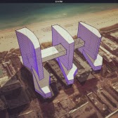
Revit revolutionized the world of Building Information Modeling by creating a platform that utilized a visual programming environment for creating parametric families and allowing for a time attribute to be added to a component to allow a fourth-dimension of time to be associated with the building model. This enables contractors to generate construction schedules based on the BIM models and simulate the construction process. One of the earliest projects to use Revit for design and construction scheduling was the Freedom Tower project in Manhattan. This project was completed in a series of separated but linked BIM models which were tied to schedules to provide real-time cost estimation and material quantities. Though the construction schedule of the Freedom Tower has been racked with political issues, improvements in coordination and efficiency on the construction site catalyzed the development of integrated software that could be used to view and interact with architects, engineers and contractors models in overlay simultaneously.
SketchBook® Pro 6
Autodesk® SketchBook® Pro sketching software for Windows or Mac computers is a fun and intuitive paint and drawing app, and can transform your computer into an ideal artist’s toolkit. With tools designed for professional artists, llustrators, and designers, the easy-to-use interface can help unlock the artist in everyone. SketchBook Pro is specifically designed to work with pen tablets, such as Wacom® Bamboo™, Intuos®, and Cintq® products, or with Windows® tablet devices to deliver an authentic drawing experience.
SketchBook® Pro 6 Features
Streamlined interface delivers an unobstructed and discoverable environment, keeping you in the creative zone.
Multitouch navigation support on the latest Wacom devices.
Synthetic paintbrushes that behave more like traditional paint mediums.
Smudge brushes for blending colors. Even more brush controls to customize.
Free up the sketching process with ultra-responsive digital pencils, pens, markers, paintbrushes, and airbrushes. Even customize your own brushes.
Draw Styles & Guide tools, like French curves, help you create clean and nearly precise strokes.
Layers let you build up and organize a drawing.
Familiar tools, like pencils, paintbrushes, markers, airbrushes, erasers, flood fill tools, and smudge brushes make it easier to get started.
Easy access to tools and commands in the intuitive and customizable menus.
A brief history of Building Information Modeling, the software that has disrupted traditional methods
of representation and collaboration in architecture.
Building Information Modeling (BIM) is a term that has become ubiquitous in the design and construction fields over the past 20 years, but where did it come from? The story is rich and complex with players from the United States, Western Europe and the Soviet Block competing to create the perfect architectural software solution to disrupt 2-Dimensional CAD workflows. The benefits of an architectural design model tied to a relational database have proven to be incredibly valuable, with contractors becoming the primary drivers of BIM technology for the first time in 2013.
What exactly is BIM?
The question often arises, for the purposes of this article, BIM software must be capable of representing both the physical and intrinsic properties of a building as an object-oriented model tied to a database . In addition most BIM software now features rendering engines, an optimized feature specific taxonomy and a programming environment to create model components. The user can view and interact with the model in three-dimensional views as well as orthographic two-dimensional plan, sections and elevation views of the model. As the model is developed, all other drawings within the project will be correspondingly adjusted. A Building Information Model could be designed in a software that is not strictly speaking, ‘parametric’ and where all information and geometry is explicitly defined but this would be cumbersome.
A parametric building modeler will allow the user to create constraints such as the height of a horizontal level, which can be tied to the height of specified set of walls and adjusted parametrically, creating a dynamic database model which is tied to geometry. This development answered a need in the architectural industry to be able to change drawings at multiple scales and across fragmented drawing sheets. The amount of hours that are necessary for the production of drawings has decreased steadily over time with the general trend of non-farm labor in the United States since 1964. The improvement in productivity has risen in concert with computer technology which has automated tedious tasks in all disciplines. Although some of the earliest programs for architectural representation used a BIM metaphor, limitations in computer power and awkward user interfaces for BIM platforms contributed to a growth in two-dimensional line drawing programs such as AutoCAD and Bentley Microstation.
Early Days
The conceptual underpinnings of the BIM system go back to the earliest days of computing. As early
as 1962, Douglas C. Englebart gives us an uncanny vision of the future architect in his paper Augmenting Human Intellect, the architect next begins to enter a series of specifications and data–a six-inch slab floor, twelve-inch concrete walls eight feet high within the excavation, and so on. When he has finished, the revised
scene appears on the screen. A structure is taking shape. He examines it, adjusts it… These lists grow into an evermore-detailed, interlinked structure, which represents the maturing thought behind the actual design.
Englebart suggests object based design, parametric manipulation and a relational database; dreams that would become reality several years later. There is a long list of design researchers whose influence is considerable including Herbert Simon, Nicholas Negroponte and Ian McHarg who was developing a parallel track with Geographic Information Systems (GIS). The work of Christopher Alexander would certainly have had an impact as it influenced an early school of object oriented programming computer scientists with Notes on the Synthesis of Form. As thoughtful and robust as these systems were, the conceptual frameworks could not be realized without a graphical interface through which to interact with such a Building Model.
Visualizing the Model From the roots of the SAGE graphical interface and Ivan Sutherland’s Sketchpad program in 1963, solid modeling programs began to appear building on developments in the computational
representation of geometry. The two main methods of displaying and recording shape information that began to appear in the 1970s and 1980s were constructive solid geometry (CSG) and boundary representation (brep). The CSG system uses a series of primitive shapes that can be either solids or voids, so that the shapes can combine and intersect, subtract or combine to create the appearance of more complex shapes. This development is especially important in representing architecture as penetrations and subtractions are common procedures in design, (windows, doors).
The process of design requires a visceral connection to the medium that the designer is working in.This posed another challenge as architects required a way to tell the computer what to do that was less tedious than the punch cards that were used on early computers. The development of light pens, head-mounted displays and various contraptions in the early days of human-computer interaction (HCI) are well documented elsewhere. A rigorous history of HCI from an architectural perspective can be found in Nicholas DeMonchaux’s book, Spacesuit: Fashioning Apollo. The text carves a narrative of the precursors to BIM and CAD technology as they were entwined in the Space Race and Cold War.
Database Building Design
Seeing buildings through the lens of the database contributed to the breakdown of architecture into its constituent components, necessitating a literal taxonomy of a buildings constituent parts. One of the first projects to successfully create a building database was the Building Description System (BDS) which was the first software to describe individual library elements which can be retrieved and added to a model. This program uses a graphical user interface, orthographic and perspective views and a sortable database that allows the user to retrieve information categorically by attributes including material type and supplier. The project was designed by Charles Eastman who was trained as an architect at Berkeley and went on to work in computer science at Carnegie Melon University.
Eastman continues as expert in BIM technology and Professor at the Georgia Tech School of Architecture. Eastman claims that drawings for construction are inefficient and cause redundancies of one object that is represented at several scales. He also criticizes hardcopy drawings for their tendency to decay over time and fail to represent the building as renovations occur and drawings are not updated. In a moment of prophecy, the notion of automated model review emerges to “check for design regularity”
in a 1974 paper.
Virtual Building
While the developments were happening rapidly in the United States, the Soviet Block had two programming geniuses who would end up defining the BIM market as it is known today. Leonid Raiz and Gábor Bojár would go on to be the respective co-founder and founder of Revit and ArchiCAD. ArchiCAD developed in 1982 in Budapest, Hungary by Gábor Bojár, a physicist who rebelled against the communist government and began a private company. Gábor wrote the initial lines of code by pawning his wife’s jewelry and smuggling Apple Computers through the Iron Curtain (Story). Using similar technology as the Building Description System, the software Radar CH was released in 1984 for the Apple Lisa Operating System. This later became ArchiCAD, which makes ArchiCAD the first BIM software that was made available on a personal computer. The software was slow to start as Bojár had to struggle with a unfriendly business climate and the
limitations of personal computer software, so ArchiCAD was not used on large scale projects until much later. ArchiCAD has made substantial gains in user base from 2007-2011, mainly as a tool for developing residential and small commercial projects in Europe. Recent improvements have made ArchiCAD a major player in the market though fundamental issues such as a lack of a phasing component and a complicated (but flexible) programming environment for its family components using GDL (Geometric Description Language) remain. To date, Graphisoft claims that more than 1,000,000 projects worldwide have been designed using ArchiCAD. Not long after Graphisoft began to sell the first seats of Radar CH, Parametric Technology Corporation (PTC) was founded in 1985 and released the first version of Pro/ENGINEER in 1988.
This is a mechanical CAD program that utilizes a constraint based parametric modeling engine. Equipped with the knowledge of working on Pro/ENGINEER, Irwin Jungreis and Leonid Raiz split from PTC and started their own software company called Charles River Software in Cambridge, MA. The two wanted to create an architectural version of the software that could handle more complex projects than ArchiCAD. They hired David Conant as their first employee, who is a trained architect and designed the initial interface which lasted for nine releases. By 2000 the company had developed a program called ‘Revit’, a made up word that is meant to imply revision and speed, which was written in C++ and utilized a parametric change engine, made possible through object oriented programming. In 2002, Autodesk purchased the company and began to heavily promote the software in competition with its own object-based software ‘Architectural Desktop’.
Revit revolutionized the world of Building Information Modeling by creating a platform that utilized a visual programming environment for creating parametric families and allowing for a time attribute to be added to a component to allow a fourth-dimension of time to be associated with the building model. This enables contractors to generate construction schedules based on the BIM models and simulate the construction process. One of the earliest projects to use Revit for design and construction scheduling was the Freedom Tower project in Manhattan. This project was completed in a series of separated but linked BIM models which were tied to schedules to provide real-time cost estimation and material quantities. Though the construction schedule of the Freedom Tower has been racked with political issues, improvements in coordination and efficiency on the construction site catalyzed the development of integrated software that could be used to view and interact with architects, engineers and contractors models in overlay simultaneously.
Towards a Collaborative Architecture
There has been a trend towards the compositing of architectural files with those of engineers who create the systems to support them which has become more prevalent within the past seven years as Autodesk has released versions of Revit specifically for Structural and Mechanical engineers. This increased collaboration has had impacts on the larger industry including a movement away from design-bid-build contracts towards integrated project delivery where many disciplines typically work on a mutually accessible set of BIM models that are updated in varying degrees of frequency. A central file takes an object and applies an attribute of ownership so that a user who is working on a given project can view all objects but can only change those that they have checked out of a ‘workset’. This feature released in Revit 6 in 2004, enables large teams of architects and engineers to work on one integrated model, a form of collaborative software. There are now several firms working towards visualization of BIM models in the fieldusing augmented reality A broad variety of programs used by architects and engineers makes collaboration difficult. Varying file formats lose fidelity as they move across platforms, especially BIM models as the information is hierarchical and specific. To combat this inefficiency the International Foundation Class (IFC) file format was developed in 1995 and has continued to adapt to allow the exchange of data from one BIM program to another. This effort has been augmented by the development of viewing software such as Navisworks which is solely designed to coordinate across varying file formats. Navisworks allows for data collection, construction simulation and clash detection and is used by most major contractors in the US today. Following in the footsteps of the Building Design Advisor, simulation programs such as Ecotect, Energy Plus, IES and Green Building Studio allow the BIM model to be imported directly and results to be gathered from simulations. In some cases there are simulations that are built directly into the base software, this method of visualization for design iteration has been introduced to Autodesk’s Vasari, a stand alone beta program similar to the Revit Conceptual Modeling Environment where solar studies and insolation levels can be calculated using weather data similar to the Ecotect package. Autodesk, through their growth and acquisition of a broad variety of software related to BIM have contributed to the expansion of what is possible from analysis of a model. In late November 2012, the development of formit, an application that allows the conceptual beginnings of a
BIM model to be started on a mobile device is a leap for the company.
Contemporary Practice and Design Academics
Some have taken a negative stance on BIM and parametrics as they assume so much about the design process and limit any work produced to the user’s knowledge of the program. This can enable a novice designer who has learned how to perform basic commands to become an incredibly prolific producer while a highly educated and experienced architect can be crippled from inexperience with a programs interface or underlying concepts. This creates a potential for a generational break line that becomes more harsh as a new technology gains market parity.Some BIM platforms that have a small market share but have made big impacts on the world of design include Generative Components (GC), developed by Bentley Systems in 2003, and Digital Project (DP). The GC system is focused on parametric flexibility and sculpting geometry and supports NURBS surfaces. The interface hinges on a node-based scripting environment that is similar
to Grasshopper to generate forms. Digital Project is a similar program was developed by Gehry Technologies around 2006 based on CATIA, a design program (and one of the first CAD programs) that was developed as an in house project by Dessault systems, a French airplane manufacturer. These two platforms have spawned something of a revolution in design as the power to iterate and transform has resulted in especially complex and provocative architectural forms. Patrick Schumacher has coined the movement of parametric building models in architecture, specifically those which allow for NURBS surfaces and scripting environments as ‘parametricism’ in his 2008 ‘Parametricist Manifesto’. “The current stage of advancement within parametricism relates as much to the continuous advancement of the attendant computational design technologies as it is due to the designer’s realization of the unique formal and organizational opportunities that are afforded. Parametricism can only exist via sophisticated parametric techniques. Finally, computationally advanced design techniques like scripting (in Mel-script or Rhino-script) and parametric modeling (with tools like GC or DP) are becoming a pervasive reality. Today it is impossible to compete within the contemporary avant-garde scene without mastering these techniques.” Since these techniques have become increasingly complex there has become a component of architectural schools which is specified to train in specific software. A student with knowledge of only one type of software platform may well be trained to design according to the biases of the programs that they are using to represent their ideas. Software performs useful tasks by breaking down a procedure into a set of actions that have been explicitly designed by a programmer. The programmer takes an idea of what is commonsense (Sack 14) and simulates a workflow using tools available to them to create an idealized goal. In the case of BIM tools, the building is represented as components including walls, roofs, floors, windows, columns, etc. These components have predefined rules or constraints which help them perform their respective tasks.
BIM platforms typically represent walls as objects with layers, these layers are defined in terms of the depth and height of a wall and are extruded along the length of a line. The program then has the ability to calculate the volume of material contained within the wall assembly and to create wall sections and details easily. This type of workflow is based on the existing building stock and common industry standards and therefore a project which is produced in a BIM platform which emphasizes these tools is likely to reinforce existing paradigms rather than develop new ones. Additionally, the programmers who worked on the early BIM platforms often did not have a background in architecture but employed hybrid architect/programmers who contributed to the development of the programs. One notable exception I have found to this is the work of Charles Eastman who received a Masters of Architecture from Berkeley before working on the Building Description System. The roots of the major BIM platforms that are in use today have been developed by programmers with the peripheral input of hybrid programmer/architects and a global user base who contributes to the development of the software via ‘wish lists’ or online forums where grievances can be aired about a product workflow. The grievances typically result in new features and build upon the existing interface. Though the general concept and technology behind BIM is approaching its thirtieth anniversary, the
industry has only begun to realize the potential benefits of Building Information Models. As we reach a point where a majority of buildings are being crafted digitally, an existing building marketplace where building materials and structural components can be bought and sold locally will emerge. Sustainable design practices reinforce an attitude of designing for disassembly and a marketplace of these parts is essential. Trends in Human Computer Interaction, Augmented Reality, Cloud Computing,Generative Design and Virtual Design and Construction continue to rapidly influence the development of BIM. Looking back at the past it is easier to realize that the present moment is an exciting time for designers and programmers in this evolving industry.
FREE ONLINE TRAINING DEMO IN Revit and BIM softwares.... Log into www.cadcim.com or write to us at sale@cadcim.com (219 2284908)
Autodesk® FormIt mobile app helps you capture building design concepts digitally anytime, anywhere ideas strike. Use real-world site information to help create forms in context and support early design decisions with real building data. Experience a continuous Building Information Modeling (BIM) workflow by synchronizing designs in the cloud for further refinement using Autodesk® Revit® software products and other applications.
Express design ideas with easy-to-use tools:
Create forms quickly from a gallery of shapes
Directly manipulate forms using gestures for easy model changes
Save designs to the cloud and share with others
Easy access to site information:
Set project location in a searchable maps interface
Import satellite image of your site
Design directly in the context of your proposed building location
Make early design decisions:
Explore the effects of the sun using the location-aware Shadow Study tool
Start early program analysis by tracking gross building floor area ratio while you design
Experience a more continuous BIM workflow:
Store and share designs in the cloud using Autodesk® 360 cloud services
Easily transfer designs to desktop applications via RVT or SAT file formats
Explore design ideas and add detail to early design forms using award-winning BIM technology
Pretty Interesting new set of feature in Revit
Architecture is, Point Cloud. Point Cloud is basically a collection of data in
X,Y, and Z ordinates. You can collect this data by 3D scanners and then these
3D scanned point clouds will help you to create 3D models.
Point
cloud files are .rcp and .rcs type format files. If the file is in raw format
such as .pcg or .las format, then you will be prompted to index the data. The
indexed point cloud file will then be converted into .rcp and .rcs format files
which is further inserted in a Revit project. After inserting the point cloud
file, you will use that file in the project. This file helps the user to
provide a higher level of visual appearance of existing condition of a
building. To view the existing building, capture it using laser scanners. Laser
Scanners are used to sample point from the surface of the existing building and
saves that data as point cloud. The data collected by the laser scanner is
huge. Thus, Revit links a point cloud as a reference rather than embedding the
complete file. Now, the existing building will be loaded in a project in the
form of 3D scanned point cloud. Therefore, you can modify the existing building
condition easily and the work performance will also be improved due to better
visibility.
Revit Architecture 2014 affords you with one of the exciting tool, i.e. convert Stair Component to Sketch. This feature aids you to convert the stair component to sketch and to design the stair component of your own style.
Figure 1: Creating a Stair Component
Let us know how we can create a stair component and then to convert it into the sketched form to edit and create your own stair. Here are the following steps to be followed to draw a stair component and then to convert them into sketch form.
1.Open Revit Architecture 2014 session. The user interface screen will display.
2.Now, invoke the Stair by Component tool from the Build panel of the Architecture tab, as shown in Figure 1; the Modify | Create Stair tab will be displayed.
3.In the Modify|Create Stair tab, choose the Run tool and draw stair in the drawing area, as how in Figure 2.
4.Now, create another run running parallel to it, Revit will automatically generate landing between the two runs, as shown in Figure 3.
5.After creating complete stair, choose the Finish Edit Mode button from the Mode panel of the Modify|Create Stair tab.
6.Now, choose the Default 3D view tool from the Quick Access Toolbar the 3D view of a stair will be displayed, as shown in Figure 4.
Figure 2: Converting Component into Sketch
1.To convert a stair component to sketch, enter into the floor plan of your project.
2.Select the stair component; the Modify | Stairs tab is displayed.
3.Choose the Edit Stairs tool from the Edit panel of this tab, you will enter into the sketch form.
4.Now, select the run which is to be modified and select the Convert tool, as shown in Figure 5. On doing so, the Stair- Convert to Custom window is displayed.
5.Choose the Close button. Now, you are in custom sketch form.
6.Choose the Edit Sketch tool from the Tools panel; the Modify|Create Stair > Sketch Run contextual tab is displayed.
7.Now, from here you can modify the run by using the tools from the Draw panel of this tab.
You can read more detail of this topic on our latest text book Autodesk Revit Architecture 2014 for Architects and Designers
For more detail and know about our latest textbook log on to www.cadcim.com
Property Mapping in Navisworks 2015
-
- Property Mapping allows you to map the takeoff properties to the model
properties for the entire item calculations.
- It can be used by c...


.jpg)


.jpg)


.png)

.png)

.png)


.jpg)

.jpg)


