


Sunday, December 22, 2013
Friday, December 20, 2013
Project Location- Vasari
When you
create a project it is possible to specify the geographic location using the
street address or the latitude and longitude. This is useful for generating
location-specific shadows for views that use them, such as solar studies and
walkthroughs. The location provides a basis for weather information, which is
used during conceptual energy analysis.
To
specify the project location, Analyze tab > Project Location panel > Location.
When your computer is connected to the Internet, and you have signed in to
Autodesk online services, this dialog displays an interactive map through the
Google Maps mapping service. To sign in see Autodesk
Account.
Until you specify a different project
location, the location is set to the longitude and latitude of the major city
specified by Vasari for your locale.
For the
Project Address, enter the street address, city and country. For Example- Enter: Fulton Street & Pearl Street,
Woodbridge Township, NJ 07095, USA

Click Import Site Image to import the Google map image of your
location into your project file.
You can also access this dialog from the Sun Settings dialog, the
Energy Settings dialog or in the drawing area, underneath the ViewCube, click
the current location > Set Location.
Use the following tools to adjust the map as needed:
§
Pan. When you place the cursor over the map, the cursor changes to
a hand, and you can drag the map to pan the view. For Zoom, Click + (Zoom
in) or - (Zoom out), or drag the zoom slider to adjust the
zoom level.
§
Map. Shows street map.
§
Satellite. Shows satellite imagery.
§
Terrain. Default view. Shows street map superimposed on
topographical map.
Friday, December 13, 2013
Wednesday, December 11, 2013
Curtain Panel Pattern Based- Autodesk Vasari
Vasari Introduction
Project Vasari is a standalone application that expands on the Revit conceptual mass family interface. Autodesk Project Vasari facilitates you with the curtain panel pattern based family. In this, you can create families of different shapes and patterns. Decorative panel can be obtained from the curtain panel pattern based family. These are project hosted elements. You can create panel and then it is to be loaded either on the adaptive component or in project environment.
Project Vasari is a standalone application that expands on the Revit conceptual mass family interface. Autodesk Project Vasari facilitates you with the curtain panel pattern based family. In this, you can create families of different shapes and patterns. Decorative panel can be obtained from the curtain panel pattern based family. These are project hosted elements. You can create panel and then it is to be loaded either on the adaptive component or in project environment.
Steps to Create Family and load it in Adaptive
Component Family.
1. Open
the Curtain Panel Pattern Based Family from the Application Menu.

2. The
Rectangular curtain panel is displayed, by default.
3. Choose
the pattern and then change that pattern into rhomboid from the Type Selector
drop-down list.
4. The
pattern is converted into rhomboid structure and change the Vertical spacing to
15’ in the Properties palette.

5. Now,
place a point on the pattern and set the work plane vertically on that point.

6. Accordingly,
draw the rectangle on that workplane.
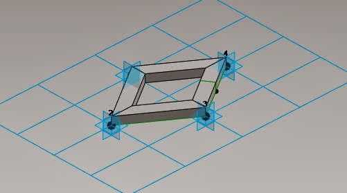
7. Now,
choose the drawn rectangle and the rhomboid pattern and then choose the Solid
Form tool from the Create Form drop-down; the new pattern is formed.

8. Now,
load the project into the adaptive component family.
9. After loading the family, draw any solid form
and divide the surface.
10. Now,
select the complete element and select the family from the Properties palette.
11. The Family is loaded and the Curtain Panel
Pattern based component is created.

Barriers to Building Information Modeling
Barriers to BIM
The ultimate objective is to build an integrated BIM—a virtual building before we make expensive mistakes with concrete, glass and steel. But tradition, contractual separation, archaic laws, technical limitations, interoperability problems and culture hinder us.
Software and hardware constraints: A BIM model theoretically has unlimited ability to hold information. But any practical project model will fall short of what is theoretically possible. Despite faster and faster computers and more efficient software, the model slows down as it enlarges.
Cost practicalities: At some point, it becomes impractical to add detail to the model. We still assume the builder will use some judgment in the field. A drawing doesn’t need to show all the nail locations in a wood frame.
Universal adaption: The fruition of BIM will depend on widespread use by designers, contractors and manufacturers. But until trade contractors and manufacturers are operational with BIM, we will limp along with incomplete integration.
Interoperability: Any CM or PM that has managed a program that included multiple architects and multiple CMs has faced the frustrating problems of interoperability in trying to integrate data from different project management information systems. It is hard to share data between Autodesk’s Constructware, e-Builder and Meridian’s Prolog. The same problem exists with BIM software.
A fully integrated BIM model is a vision, not a reality. At current levels of development, architects engineers, consultants, builders and fabricators may have independent BIM models, legacy CAD systems and legacy paper systems. Those who use BIM software may not use the same programs
The ultimate objective is to build an integrated BIM—a virtual building before we make expensive mistakes with concrete, glass and steel. But tradition, contractual separation, archaic laws, technical limitations, interoperability problems and culture hinder us.
Cost practicalities: At some point, it becomes impractical to add detail to the model. We still assume the builder will use some judgment in the field. A drawing doesn’t need to show all the nail locations in a wood frame.
Universal adaption: The fruition of BIM will depend on widespread use by designers, contractors and manufacturers. But until trade contractors and manufacturers are operational with BIM, we will limp along with incomplete integration.
Interoperability: Any CM or PM that has managed a program that included multiple architects and multiple CMs has faced the frustrating problems of interoperability in trying to integrate data from different project management information systems. It is hard to share data between Autodesk’s Constructware, e-Builder and Meridian’s Prolog. The same problem exists with BIM software.
A fully integrated BIM model is a vision, not a reality. At current levels of development, architects engineers, consultants, builders and fabricators may have independent BIM models, legacy CAD systems and legacy paper systems. Those who use BIM software may not use the same programs
BIM Model Management
Managing a BIM Model
Managing a Building Information
Model is similar to managing an actual model in site. A construction manager must understand the
technology of construction. But the more crucial job is orchestrating the work
of hundreds of organizations—coordinating the assembly of materials on-site
with decision-making, sequencing, and supply chain management.
Most of a project is built off-site. If the
on-site management team doesn’t manage the off-site activities there will be delays.
Managing the interrelationships is as important as understanding the technology
of the work. In the simplest sense, it doesn’t do any good for a construction
superintendent to know about forming and finishing concrete if the concrete
truck isn’t scheduled for delivery at the right time.
A BIM model has similar
requirements. Managing the development of a virtual construction model requires
skills that are similar to managing the real thing. Too often BIM production is
staffed with people who understand BIM technology but don’t understand how to
manage the workflow from multiple sources.
The management job requires
setting BIM standards, understanding constructibility and construction
sequence, evaluating supply chain data and vetting information that is
submitted to be input into the model. But most of all, it requires
understanding how to suck this information from multiple sources into an
integrated model. The manager must have clout in the organization to get the
attention of the extended IPD team to schedule information flow, analysis and
problem solving. And since inputs to a BIM model may ricochet through the
model, the manager must review and evaluate the accuracy of inputs—just as a
CFO ensures that there are procedures to evaluate the inputs of financial
information before they are posted to a general ledger.
A BIM model manager requires the
support of the IPD management committee who must set policies to adopt the
technology, buy and install the software for members who do not have it, train
the team, champion the use. Finally, they will need to establish workflows for
a BIM process that may be developed by the BIM model manager.
An IPD team needs a BIM manager
and an interdisciplinary BIM team staffed with people from member firms. The
BIM team integrates drawings from the AEs, subs and manufacturers. They develop
4D and 5D models. They detect coordination problems with clash detection
routines. Constructibility reviews trigger design adjustments—made with the
collaboration of the AEs. RFIs are anticipated and if collaboration ongoing,
should be minimal. In developing the model, questions surface before
construction.
The BIM model manager must be a
person with good interpersonal skills to build the collaborative culture
required to produce an integrated BIM model. The manager must build trust and
networks of personal communication within the contracting team. As with real
construction, the more personal contact and the more trust, the more
collaboration. BIM allows trust to be built early, well before construction
begins. There’s an opportunity to allocate model space to each subcontractor to
give them confidence that the process will not only find clashes in their
systems before they get to the field, but that the sub will have the ability to
model the clearances and working space needed to install their work.
Architects have typically been
the primary source of BIM models, fulfilling their traditional role in
developing the drawings and specifications that document the product—the
description of the design, the intended physical result.
CMs have usually taken the lead
in providing project management information (PMIS) systems—gathering and
integrating data from the extended project team. These systems have
concentrated on process—tracking contractual matters such as cost, schedule and
quality control; RFIs and change orders.
But now CMs are developing
in-house BIM teams and are developing BIM models prior to construction.2
Eventually, it is likely that an
IPD Core Team will build integrated groups to produce integrated documents.
Clearly, managing virtual construction will require technical knowledge of both
process and product. Virtual construction will require AEs with product
expertise and CMs with process expertise.
BIM in Industry
BIM Characteristics
A BIM model is a digital description of a project. It may
include information such as the physical configuration, programmatic
requirements, functional characteristics, specifications, systems performance,
supply chain threads, construction sequence, cost or any other information that
might be useful.
Plug-ins:
Specialized software may be “plugged in”
with algorithms that can adjust related building systems if there is a design
change. These “plug ins” can include programs for structural and mechanical
design. For instance, if a room is enlarged, the size of the structural members
can be automatically recalculated and resized. The model adjusts itself. If the
building is rotated on the site, the heat gain and loss may be recalculated.
Other plug-ins may focus on energy analysis, LEED certification, cost
estimating or construction scheduling.
Reports:
BIM ideologues will
quickly tell you that BIM is not drafting software. It is a database. Drawings
are simply one form of report. Like any digital database, a BIM model can
produce reports—subsets of information for special purposes. These reports can
be in the form of 2D or 3D drawings or an infinite variety of custom
alphanumeric reports. The IPD team can tailor reports for specific purposes
instead of grappling with a large set of 30” x 40” construction drawings and a
fat set of specifications that obscures required information.
For instance, architects can produce a report in 3D and in
color, rendered for comprehension by non-technical people. They can deliver
drawings for review by entitlement agencies (building permits, accessibility
requirements, environmental concerns, aesthetic compatibility or whatever) that
address the agency’s specific requirements. Assembly details can be produced on
site for current construction challenges. Facility managers may access
life-cycle, maintenance and replacement information.
4D and 5D models:
BIM can have sequence and construction
duration information attached to drawing elements that represent the building
systems (4D modeling). A computer program can animate construction progression.
A user can input a date to observe current state of completion. The builder can
analyze on-site material staging problems, develop phasing plans, improve the
sequencing of trade contractors or analyze the cost of construction delays.
Cost can also be attached to drawing elements that represent building systems (5D
modeling) for estimating and value engineering. The estimate can progress in
lockstep with design.
Clash Detection:
At the simplest level, pasting shop drawings into a CAD
drawing quickly indicates a misalignment or a poor fit. Even in a 2D model, it
is obvious if a window doesn’t fit between a pair of columns. However, problems
are not always that obvious in 2D models. Conflicts are often caused when a
building system designed by one consultant interferes with a system designed by
another
consultant on separate drawings. For instance, if a lighting
consultant locates recessed light fixtures on an architectural reflected
ceiling plan without checking beam locations on structural drawings, the
recessed can may poke into a beam. And we have all experienced a mechanical
engineer plotting duct runs that pass through the structural engineers’ beams.
BIM software provides sophisticated “clash detection” routines that indicate
when two systems or products occupy the same space.
Direct fabrication control:
Traditionally, fabricators
develop shop drawings based on their interpretation of the plans and
specifications. They are checked by the AE. Errors occur at each translation.
By pasting shop drawings directly into the BIM model, errors and conflicts are
more apt to be detected. Ultimately, a BIM model may include algorithms for
CNC.
Facilities
Management:
An integrated BIM
model is a good bit more valuable to facility managers than typical “as built”
drawings. It may contain warranty data, spare parts lists and sources, useful
life expectations and maintenance recommendations. It may contain original
layouts as well as remodeling and renovation documentation. direct fabrication
of building systems, such as ductwork, curtain wall, millwork. While there are
still opportunities for error in these automated processes, they are reduced
and often eliminated. Precision is increased and supply chain workflow is
shortened.
BIM as a contract
tool:
Although IPD may minimize the contractual silos between the
members, it is unlikely that an IPD team will include 50 to 75 subcontractors.
Contractual separation will remain for most of the design and construction
team. Multiple customized reports from a BIM model will assume important roles
as contractual tools. The tools will work both ways—clarifying agreements with
both the owner and with subcontractors.
The initial agreement with the owner will likely be a
written document, perhaps with some simple diagrams to describe the intended
result. As the project progresses, printed reports from the BIM can then
augment that original agreement, defining the work for staged approvals just as
traditional SD, DD or CD documents have done. However, rendered 3D reports from
the model will do a better job of ensuring a meeting of the minds with the
owner or users who may lack experience with technical Construction Documents.
Computer Numerical Control refers to computer instructions
that drive machine tools used to fabricate components. The technology is labor
efficient, accurate, repeatable and facilitates complex forms.
The BIM will then become the framework for describing the
work to subcontractors. As the design develops, subs will be asked to propose
or bid on aspects of the work. When selected, aspects of their technical
proposal may become part of the BIM—to be augmented or replaced with shop
drawings as their work is developed.
BIM Evolution
Evolution of BIM
Courtesy: YouTube
EVOLUTION
Vector CAD:
EVOLUTION
Vector CAD:
The first generations of CAD represented buildings with geometry—vector based lines, arcs and circles. A CAD drawing was easy to modify and replicate. It also provided greater precision than pencil on paper. But it was dumb: lines drawn with a computer instead of a pencil.
Object CAD: Then “smart” objects with properties were added. Objects like windows, doors, walls, roofs or stairs had properties that governed their behavior. A window could be pulled from a resource file into a drawing and stretched to fit the required opening. As it was stretched, the panes would grow but the jamb section would not. A user could associate information to the object such as the supplier, part numbers, the finish, the warranty and so on. The drawing objects were “smart.” They knew how to behave and what they were.
BIM: From that point, it was a logical step to envision an entire building as a smart object with endless possibilities for algorithms that govern its behavior and and associated information. BIM emerged.
Sunday, December 8, 2013
Quick Start Project in Revit MEP
Starting a New Project in MEP
The following are the topics covered in this tutorial:
1. Starting a New Project
2. Selecting a Template
3. Setting the Project Units
4. Setting the Location
5. Setting the Drawing area
6. Linking an Architectural Model
7. Re-organizing the Browser
http://www.youtube.com/watch?v=l4AZkRWJS9g&feature=share
This will help you to start a new project and work in an integral model in Revit Model.
For more information about our services please write to us sales@cadcim.com or
call us at 219-2284908 or visit us at www.cadcim.com
Monday, December 2, 2013
BIM 360-Software for Construction Collaboration and Management
Autodesk® BIM 360™ transforms the way construction data is
collected, connected, visualized, and managed. This cloud-based software combines
cloud and mobile technologies to manage your data from preconstruction to the
field. Improve construction collaboration to prevent issues and drive higher
quality and profitability.
It has two solutions: BIM 360 Field and BIM 360 Glue.
BIM 360 Field
It is a construction field data management software.
Field data management, commissioning, and handover.
BIM 360 Field software (formerly Vela Systems) is
construction field management software that combines mobile technologies at the
point of construction with cloud-based collaboration and reporting. Turn your
field data into information that improves quality, safety, and profitability
for construction and capital projects. This is a cloud-based service.

BIM 360 Glue
Online BIM coordination and management
BIM 360 Glue is an online BIM coordination and management
service that provides anytime, anywhere access to connected project
information. Accelerate multidiscipline collaboration, reduce coordination
review cycles, and improve project efficiency.
Welcome to Project Vasari & Green Building Studio
Autodesk
Vasari is introduced by Giorgio Vasari. Project Vasari is a lighter version of
Revit Architecture. This is an easy-to-use expressive design tool and is
primarily introduced for creating building concepts and to provide analysis for
energy and carbon.
Project Vasari focuses
on conceptual building design using both geometric and parametric modeling. It
basically creates, analyze and refine whole building models. It studies about
climate, shadow and solar radiations as well. The most important design
decisions are made depending upon the design analysis.
Green building Studio
is a web based tool. It helps in analyzing whole building energy, water, and
carbon content. It can be analyzed for anywhere like US, UK and so on.
How AutoCAD Started
Begining
AutoCAD is a software application for 2D and 3D
computer-aided design (CAD) and drafting — available since 1982 as a desktop
application and since 2010 as a mobile web- and cloud-based app, currently
marketed as AutoCAD 360. Developed and
marketed by Autodesk, Inc. AutoCAD was first released in December 1982 — having
been purchased a year prior in its original form by Autodesk founder John
Walker. The software is currently marketed in its eighteenth generation.
.jpg) |
| John Walker---Founder Autodesk |
As Autodesk's flagship product, by March 1986 AutoCAD had
become the most ubiquitous microcomputer design program worldwide, with
functions such as "polylines" and "curve fitting". Prior to
the introduction of AutoCAD, most other CAD programs ran on mainframe computers
or minicomputers, with each CAD operator (user) working at a graphical terminal
or workstation.
AutoCAD is used across a range of industries, including
architects, project managers and engineers, among other professions, with 750
training centers established worldwide as of 1994.
History of AutoCAD
History of AutoCAD
AutoCAD was derived from a 1977 program called Interact CAD,
which was written in a proprietary language (SPL) by inventor Michael Riddle
who later co-founded Autodesk to market AutoCAD. This early version ran on the Marinchip
Systems 9900 computer (Marinchip Systems was owned by Autodesk co-founders John
Walker and Dan Drake). While initially Walker and Riddle had a profits-sharing
agreement for any product derived from Interact, in the end Walker paid Riddle
US$10 million for all the rights.
 |
| Michael Riddle --Inventor of Interact CAD |
When Marinchip Software Partners (later known as Autodesk)
formed, the founders decided to re-code Interact in C and PL/1. They chose C
because it seemed to be the biggest upcoming language.[citation needed] In the
end, the PL/1 version was unsuccessful. The C version was, at the time, one of
the most complex programs in that language. Autodesk had to work with a
compiler developer, Lattice, to update C, enabling AutoCAD to run.[4] Early
releases of AutoCAD used primitive entities — lines, polylines, circles, arcs,
and text — to construct more complex objects. Since the mid-1990s, AutoCAD
supported custom objects through its C++ Application Programming Interface
(API). AutoCAD uses its own fork of the ACIS geometry modelling kernel. The
modern AutoCAD includes a full set of basic solid modeling and 3D tools. The
release of AutoCAD 2007 included the improved 3D modeling that provided better
navigation when working in 3D. Moreover, it became easier to edit 3D models.
The mental ray engine was included in rendering and therefore it is possible to
do quality renderings. AutoCAD 2010 introduced parametric functionality and
mesh modeling.
The latest AutoCAD releases are AutoCAD 2014 and AutoCAD
2014 for Mac. The 2014 release marked the 28th major release for the AutoCAD
for Windows. The 2014 release marked the fourth consecutive year for AutoCAD
for Mac.
Beginning of Revit and Archicad
Founders of the Revolution----Revit
While the developments were happening rapidly in the United States, the Soviet Block had two programming geniuses who would end up defining the BIM market as it is known today. Leonid Raiz and Gábor Bojár would go on to be the respective co-founder and founder of Revit and ArchiCAD.
 |
| Leonid Raiz--- Co-founder Revit |
ArchiCAD developed in 1982 in Budapest, Hungary by Gábor Bojár, a physicist who rebelled against the communist government and began a private company. Gábor wrote the initial lines of code by pawning his wife’s jewelry and smuggling Apple Computers through the Iron Curtain (Story). Using similar technology as the Building Description System, the software Radar CH was released in 1984 for the Apple Lisa Operating System. This later became ArchiCAD, which makes ArchiCAD the first BIM software that was made available on a personal computer.
The software was slow to start as Bojár had to struggle with a unfriendly business climate and the limitations of personal computer software, so ArchiCAD was not used on large scale projects until much later. ArchiCAD has made substantial gains in user base from 2007-2011, mainly as a tool for developing residential and small commercial projects in Europe. Recent improvements have made ArchiCAD a major player in the market though fundamental issues such as a lack of a phasing component and a complicated (but flexible) programming environment for its family components using GDL (Geometric Description Language) remain. To date, Graphisoft claims that more than 1,000,000 projects worldwide have been designed using ArchiCAD.
 |
| David Connant-First Architect of Revit |
Not long after Graphisoft began to sell the first seats of Radar CH, Parametric Technology Corporation (PTC) was founded in 1985 and released the first version of Pro/ENGINEER in 1988. This is a mechanical CAD program that utilizes a constraint based parametric modeling engine. Equipped with the knowledge of working on Pro/ENGINEER, Irwin Jungreis and Leonid Raiz split from PTC and started their own software company called Charles River Software in Cambridge, MA. The two wanted to create an architectural version of the software that could handle more complex projects than ArchiCAD. They hired David Conant as their first employee, who is a trained architect and designed the initial interface which lasted
for nine releases. By 2000 the company had developed a program called ‘Revit’, a made up word that is meant to imply revision and speed, which was written in C++ and utilized a parametric change engine, made possible through object oriented programming. In 2002, Autodesk purchased the company and began to heavily promote the software in competition with its own object-based software ‘Architectural Desktop’.
Revit revolutionized the world of Building Information Modeling by creating a platform that utilized a visual programming environment for creating parametric families and allowing for a time attribute to be added to a component to allow a fourth-dimension of time to be associated with the building model. This enables contractors to generate construction schedules based on the BIM models and simulate the construction process. One of the earliest projects to use Revit for design and construction scheduling was the Freedom Tower project in Manhattan. This project was completed in a series of separated but linked BIM models which were tied to schedules to provide real-time cost estimation and material quantities. Though the construction schedule of the Freedom Tower has been racked with political issues, improvements in coordination and efficiency on the construction site catalyzed the development of integrated software that could be used to view and interact with architects, engineers and contractors models in overlay simultaneously.
Towards a
Sketchbook----Desktop
SketchBook® Pro 6
Autodesk® SketchBook® Pro sketching software for Windows or Mac computers is a fun and intuitive paint and drawing app, and can transform your computer into an ideal artist’s toolkit. With tools designed for professional artists, llustrators, and designers, the easy-to-use interface can help unlock the artist in everyone. SketchBook Pro is specifically designed to work with pen tablets, such as Wacom® Bamboo™, Intuos®, and Cintq® products, or with Windows® tablet devices to deliver an authentic drawing experience.
SketchBook® Pro 6 Features
Streamlined interface delivers an unobstructed and discoverable environment, keeping you in the creative zone.
Multitouch navigation support on the latest Wacom devices.
Synthetic paintbrushes that behave more like traditional paint mediums.
Smudge brushes for blending colors. Even more brush controls to customize.
Free up the sketching process with ultra-responsive digital pencils, pens, markers, paintbrushes, and airbrushes. Even customize your own brushes.
Draw Styles & Guide tools, like French curves, help you create clean and nearly precise strokes.
Layers let you build up and organize a drawing.
Familiar tools, like pencils, paintbrushes, markers, airbrushes, erasers, flood fill tools, and smudge brushes make it easier to get started.
Easy access to tools and commands in the intuitive and customizable menus.
History of BIM
The Beginning.....

A brief history of Building Information Modeling, the software that has disrupted traditional methods
of representation and collaboration in architecture.
Building Information Modeling (BIM) is a term that has become ubiquitous in the design and construction fields over the past 20 years, but where did it come from? The story is rich and complex with players from the United States, Western Europe and the Soviet Block competing to create the perfect architectural software solution to disrupt 2-Dimensional CAD workflows. The benefits of an architectural design model tied to a relational database have proven to be incredibly valuable, with contractors becoming the primary drivers of BIM technology for the first time in 2013.
What exactly is BIM?
The question often arises, for the purposes of this article, BIM software must be capable of representing both the physical and intrinsic properties of a building as an object-oriented model tied to a database . In addition most BIM software now features rendering engines, an optimized feature specific taxonomy and a programming environment to create model components. The user can view and interact with the model in three-dimensional views as well as orthographic two-dimensional plan, sections and elevation views of the model. As the model is developed, all other drawings within the project will be correspondingly adjusted. A Building Information Model could be designed in a software that is not strictly speaking, ‘parametric’ and where all information and geometry is explicitly defined but this would be cumbersome.
A parametric building modeler will allow the user to create constraints such as the height of a horizontal level, which can be tied to the height of specified set of walls and adjusted parametrically, creating a dynamic database model which is tied to geometry. This development answered a need in the architectural industry to be able to change drawings at multiple scales and across fragmented drawing sheets. The amount of hours that are necessary for the production of drawings has decreased steadily over time with the general trend of non-farm labor in the United States since 1964. The improvement in productivity has risen in concert with computer technology which has automated tedious tasks in all disciplines. Although some of the earliest programs for architectural representation used a BIM metaphor, limitations in computer power and awkward user interfaces for BIM platforms contributed to a growth in two-dimensional line drawing programs such as AutoCAD and Bentley Microstation.
Early Days
The conceptual underpinnings of the BIM system go back to the earliest days of computing. As early
as 1962, Douglas C. Englebart gives us an uncanny vision of the future architect in his paper Augmenting Human Intellect, the architect next begins to enter a series of specifications and data–a six-inch slab floor, twelve-inch concrete walls eight feet high within the excavation, and so on. When he has finished, the revised
scene appears on the screen. A structure is taking shape. He examines it, adjusts it… These lists grow into an evermore-detailed, interlinked structure, which represents the maturing thought behind the actual design.
Englebart suggests object based design, parametric manipulation and a relational database; dreams that would become reality several years later. There is a long list of design researchers whose influence is considerable including Herbert Simon, Nicholas Negroponte and Ian McHarg who was developing a parallel track with Geographic Information Systems (GIS). The work of Christopher Alexander would certainly have had an impact as it influenced an early school of object oriented programming computer scientists with Notes on the Synthesis of Form. As thoughtful and robust as these systems were, the conceptual frameworks could not be realized without a graphical interface through which to interact with such a Building Model.
Visualizing the Model From the roots of the SAGE graphical interface and Ivan Sutherland’s Sketchpad program in 1963, solid modeling programs began to appear building on developments in the computational
representation of geometry. The two main methods of displaying and recording shape information that began to appear in the 1970s and 1980s were constructive solid geometry (CSG) and boundary representation (brep). The CSG system uses a series of primitive shapes that can be either solids or voids, so that the shapes can combine and intersect, subtract or combine to create the appearance of more complex shapes. This development is especially important in representing architecture as penetrations and subtractions are common procedures in design, (windows, doors).
The process of design requires a visceral connection to the medium that the designer is working in.This posed another challenge as architects required a way to tell the computer what to do that was less tedious than the punch cards that were used on early computers. The development of light pens, head-mounted displays and various contraptions in the early days of human-computer interaction (HCI) are well documented elsewhere. A rigorous history of HCI from an architectural perspective can be found in Nicholas DeMonchaux’s book, Spacesuit: Fashioning Apollo. The text carves a narrative of the precursors to BIM and CAD technology as they were entwined in the Space Race and Cold War.
Database Building Design
Seeing buildings through the lens of the database contributed to the breakdown of architecture into its constituent components, necessitating a literal taxonomy of a buildings constituent parts. One of the first projects to successfully create a building database was the Building Description System (BDS) which was the first software to describe individual library elements which can be retrieved and added to a model. This program uses a graphical user interface, orthographic and perspective views and a sortable database that allows the user to retrieve information categorically by attributes including material type and supplier. The project was designed by Charles Eastman who was trained as an architect at Berkeley and went on to work in computer science at Carnegie Melon University.
Eastman continues as expert in BIM technology and Professor at the Georgia Tech School of Architecture. Eastman claims that drawings for construction are inefficient and cause redundancies of one object that is represented at several scales. He also criticizes hardcopy drawings for their tendency to decay over time and fail to represent the building as renovations occur and drawings are not updated. In a moment of prophecy, the notion of automated model review emerges to “check for design regularity”
in a 1974 paper.
Virtual Building
While the developments were happening rapidly in the United States, the Soviet Block had two programming geniuses who would end up defining the BIM market as it is known today. Leonid Raiz and Gábor Bojár would go on to be the respective co-founder and founder of Revit and ArchiCAD. ArchiCAD developed in 1982 in Budapest, Hungary by Gábor Bojár, a physicist who rebelled against the communist government and began a private company. Gábor wrote the initial lines of code by pawning his wife’s jewelry and smuggling Apple Computers through the Iron Curtain (Story). Using similar technology as the Building Description System, the software Radar CH was released in 1984 for the Apple Lisa Operating System. This later became ArchiCAD, which makes ArchiCAD the first BIM software that was made available on a personal computer. The software was slow to start as Bojár had to struggle with a unfriendly business climate and the
limitations of personal computer software, so ArchiCAD was not used on large scale projects until much later. ArchiCAD has made substantial gains in user base from 2007-2011, mainly as a tool for developing residential and small commercial projects in Europe. Recent improvements have made ArchiCAD a major player in the market though fundamental issues such as a lack of a phasing component and a complicated (but flexible) programming environment for its family components using GDL (Geometric Description Language) remain. To date, Graphisoft claims that more than 1,000,000 projects worldwide have been designed using ArchiCAD. Not long after Graphisoft began to sell the first seats of Radar CH, Parametric Technology Corporation (PTC) was founded in 1985 and released the first version of Pro/ENGINEER in 1988.
This is a mechanical CAD program that utilizes a constraint based parametric modeling engine. Equipped with the knowledge of working on Pro/ENGINEER, Irwin Jungreis and Leonid Raiz split from PTC and started their own software company called Charles River Software in Cambridge, MA. The two wanted to create an architectural version of the software that could handle more complex projects than ArchiCAD. They hired David Conant as their first employee, who is a trained architect and designed the initial interface which lasted for nine releases. By 2000 the company had developed a program called ‘Revit’, a made up word that is meant to imply revision and speed, which was written in C++ and utilized a parametric change engine, made possible through object oriented programming. In 2002, Autodesk purchased the company and began to heavily promote the software in competition with its own object-based software ‘Architectural Desktop’.
Revit revolutionized the world of Building Information Modeling by creating a platform that utilized a visual programming environment for creating parametric families and allowing for a time attribute to be added to a component to allow a fourth-dimension of time to be associated with the building model. This enables contractors to generate construction schedules based on the BIM models and simulate the construction process. One of the earliest projects to use Revit for design and construction scheduling was the Freedom Tower project in Manhattan. This project was completed in a series of separated but linked BIM models which were tied to schedules to provide real-time cost estimation and material quantities. Though the construction schedule of the Freedom Tower has been racked with political issues, improvements in coordination and efficiency on the construction site catalyzed the development of integrated software that could be used to view and interact with architects, engineers and contractors models in overlay simultaneously.
Towards a Collaborative Architecture
There has been a trend towards the compositing of architectural files with those of engineers who create the systems to support them which has become more prevalent within the past seven years as Autodesk has released versions of Revit specifically for Structural and Mechanical engineers. This increased collaboration has had impacts on the larger industry including a movement away from design-bid-build contracts towards integrated project delivery where many disciplines typically work on a mutually accessible set of BIM models that are updated in varying degrees of frequency. A central file takes an object and applies an attribute of ownership so that a user who is working on a given project can view all objects but can only change those that they have checked out of a ‘workset’. This feature released in Revit 6 in 2004, enables large teams of architects and engineers to work on one integrated model, a form of collaborative software. There are now several firms working towards visualization of BIM models in the fieldusing augmented reality A broad variety of programs used by architects and engineers makes collaboration difficult. Varying file formats lose fidelity as they move across platforms, especially BIM models as the information is hierarchical and specific. To combat this inefficiency the International Foundation Class (IFC) file format was developed in 1995 and has continued to adapt to allow the exchange of data from one BIM program to another. This effort has been augmented by the development of viewing software such as Navisworks which is solely designed to coordinate across varying file formats. Navisworks allows for data collection, construction simulation and clash detection and is used by most major contractors in the US today. Following in the footsteps of the Building Design Advisor, simulation programs such as Ecotect, Energy Plus, IES and Green Building Studio allow the BIM model to be imported directly and results to be gathered from simulations. In some cases there are simulations that are built directly into the base software, this method of visualization for design iteration has been introduced to Autodesk’s Vasari, a stand alone beta program similar to the Revit Conceptual Modeling Environment where solar studies and insolation levels can be calculated using weather data similar to the Ecotect package. Autodesk, through their growth and acquisition of a broad variety of software related to BIM have contributed to the expansion of what is possible from analysis of a model. In late November 2012, the development of formit, an application that allows the conceptual beginnings of a
BIM model to be started on a mobile device is a leap for the company.
Contemporary Practice and Design Academics
Some have taken a negative stance on BIM and parametrics as they assume so much about the design process and limit any work produced to the user’s knowledge of the program. This can enable a novice designer who has learned how to perform basic commands to become an incredibly prolific producer while a highly educated and experienced architect can be crippled from inexperience with a programs interface or underlying concepts. This creates a potential for a generational break line that becomes more harsh as a new technology gains market parity.Some BIM platforms that have a small market share but have made big impacts on the world of design include Generative Components (GC), developed by Bentley Systems in 2003, and Digital Project (DP). The GC system is focused on parametric flexibility and sculpting geometry and supports NURBS surfaces. The interface hinges on a node-based scripting environment that is similar
to Grasshopper to generate forms. Digital Project is a similar program was developed by Gehry Technologies around 2006 based on CATIA, a design program (and one of the first CAD programs) that was developed as an in house project by Dessault systems, a French airplane manufacturer. These two platforms have spawned something of a revolution in design as the power to iterate and transform has resulted in especially complex and provocative architectural forms. Patrick Schumacher has coined the movement of parametric building models in architecture, specifically those which allow for NURBS surfaces and scripting environments as ‘parametricism’ in his 2008 ‘Parametricist Manifesto’. “The current stage of advancement within parametricism relates as much to the continuous advancement of the attendant computational design technologies as it is due to the designer’s realization of the unique formal and organizational opportunities that are afforded. Parametricism can only exist via sophisticated parametric techniques. Finally, computationally advanced design techniques like scripting (in Mel-script or Rhino-script) and parametric modeling (with tools like GC or DP) are becoming a pervasive reality. Today it is impossible to compete within the contemporary avant-garde scene without mastering these techniques.” Since these techniques have become increasingly complex there has become a component of architectural schools which is specified to train in specific software. A student with knowledge of only one type of software platform may well be trained to design according to the biases of the programs that they are using to represent their ideas. Software performs useful tasks by breaking down a procedure into a set of actions that have been explicitly designed by a programmer. The programmer takes an idea of what is commonsense (Sack 14) and simulates a workflow using tools available to them to create an idealized goal. In the case of BIM tools, the building is represented as components including walls, roofs, floors, windows, columns, etc. These components have predefined rules or constraints which help them perform their respective tasks.
BIM platforms typically represent walls as objects with layers, these layers are defined in terms of the depth and height of a wall and are extruded along the length of a line. The program then has the ability to calculate the volume of material contained within the wall assembly and to create wall sections and details easily. This type of workflow is based on the existing building stock and common industry standards and therefore a project which is produced in a BIM platform which emphasizes these tools is likely to reinforce existing paradigms rather than develop new ones. Additionally, the programmers who worked on the early BIM platforms often did not have a background in architecture but employed hybrid architect/programmers who contributed to the development of the programs. One notable exception I have found to this is the work of Charles Eastman who received a Masters of Architecture from Berkeley before working on the Building Description System. The roots of the major BIM platforms that are in use today have been developed by programmers with the peripheral input of hybrid programmer/architects and a global user base who contributes to the development of the software via ‘wish lists’ or online forums where grievances can be aired about a product workflow. The grievances typically result in new features and build upon the existing interface. Though the general concept and technology behind BIM is approaching its thirtieth anniversary, the
industry has only begun to realize the potential benefits of Building Information Models. As we reach a point where a majority of buildings are being crafted digitally, an existing building marketplace where building materials and structural components can be bought and sold locally will emerge. Sustainable design practices reinforce an attitude of designing for disassembly and a marketplace of these parts is essential. Trends in Human Computer Interaction, Augmented Reality, Cloud Computing,Generative Design and Virtual Design and Construction continue to rapidly influence the development of BIM. Looking back at the past it is easier to realize that the present moment is an exciting time for designers and programmers in this evolving industry.
FREE ONLINE TRAINING DEMO IN Revit and BIM softwares.... Log into www.cadcim.com or write to us at sale@cadcim.com (219 2284908)
Autodesk Formit--------Conceptual Massing Tool
Autodesk Formit
Autodesk® FormIt mobile app helps you capture building design concepts digitally anytime, anywhere ideas strike. Use real-world site information to help create forms in context and support early design decisions with real building data. Experience a continuous Building Information Modeling (BIM) workflow by synchronizing designs in the cloud for further refinement using Autodesk® Revit® software products and other applications.
Express design ideas with easy-to-use tools:
- Create forms quickly from a gallery of shapes
- Directly manipulate forms using gestures for easy model changes
- Save designs to the cloud and share with others
Easy access to site information:
- Set project location in a searchable maps interface
- Import satellite image of your site
- Design directly in the context of your proposed building location
Make early design decisions:
- Explore the effects of the sun using the location-aware Shadow Study tool
- Start early program analysis by tracking gross building floor area ratio while you design
Experience a more continuous BIM workflow:
- Store and share designs in the cloud using Autodesk® 360 cloud services
- Easily transfer designs to desktop applications via RVT or SAT file formats
- Explore design ideas and add detail to early design forms using award-winning BIM technology

.jpg)


.png)

.png)

.png)


.jpg)

.jpg)

Subscribe to:
Posts (Atom)


