Order E Book -Revit Structure

Learn Civil/GIS Software

CAD/CAM/CAE Software Services.

Trainings

Training Services.

BIM

BIM Services.

This is default featured slide 4 title

Go to Blogger edit html and find these sentences.Now replace these sentences with your own descriptions.

.

Wednesday, December 24, 2014

Creating Model and Attached Detail Group

Autodesk Revit allows you to group all dimensions, tags, and the detail components as an attachment to the model group. This attached group consists of dimensions, tags, details lines, or detail components that refer to the model group. To create an attached revit detail group, select the model elements and detail elements simultaneously using a crossing window. As a result, the Modify| Multi-Select tab will be displayed.

You are required to choose the Create Group tool to create the group of selected model. You can choose this tool from the Create panel of the Modify|Multi Select tab; the Create Model and Attached Detail Group dialog box will be displayed. Enter the desired name of model group in the Name edit box of the Model Group area. Next, enter the detail group in the Name edit box of the Attached Detail Group area and choose the OK button; the attached detail group will be created consisting of the detail components, dimensions and detail elements. On creating the model group the designed model group will be created consisting of detail components, dimensions and detail elements.

Introduction of BIM 360 in Revit Architecture 2015


In Revit Architecture 2015, BIM 360 has been introduced as an add-in. BIM 360 is a cloud based BIM management and collaboration solution.

BIM 360 is purposely used for publishing models on the BIM 360 cloud and for sharing latest project information within a team. This add-in allows you to perform several functions such as opening model from BIM 360 Glue to Architecture, appending models from BIM 360 Glue to the current model in Architecture, and sharing models with BIM 360 Glue.


New courses on Autodesk Simulation for AEC Applications

These courses can help you confidently get started with Simulation CFD today. After learning the fundamentals, dive into common AEC applications like datacenters and HVAC design. This new series of online courses is based on this new publication: Intro to Simulation CFD for AEC Applications, which is freely available without logging in.
The series of online courses includes quizzes to tests and track your knowledge, and requires registration. The 6 new courses, available now, are:
  1. Simulation CFD Fundamentals 1: Simulation Process, Geometry, and Materials
  2. Simulation CFD Fundamentals 2: Boundary Conditions and Meshing
  3. Simulation CFD Fundamentals 3: Solving and Results Interpretation
  4. Simulation CFD Applied: Characterizing AEC Components
  5. Simulation CFD Applied: Datacenters
  6. Simulation CFD Applied: HVAC Layout
To learn more about each of the courses, click here, and scroll down the page a bit to find all Sim CFD courses.

Monday, April 21, 2014

Top Revit 2015 Enhancements

1. Username:

 Now, in Revit 2015 username will be the signed in identity. If you use the worksharing on Revit 2015 models and you are logged into the Autodesk 360 Cloud Services then the Username will be the Autodesk ID.

2.Sketchy lines: 

 The new Sketchy Lines feature in Revit 2015 is to apply a hand-sketched graphic style to the current view, or define the settings in a view template to apply the style to multiple views.

3. Anti-aliasing:

In earlier version of revit, anti-aliasing could be turned on and off only by using the Options Bar. Now in Revit 2015, you can choose this by views. As a result, it gives a better overall performance.

4. Sketchy Lines

Revit 2015 now has an extra sketchy line feature. In Revit 2015, each model view have this feature enabled. This can be enabled in the Graphic Display Options dialog box (see image below).
                                                    
In the Graphic Display Optons dialog box, there is a sketchy lines section. In the Graphic Display Options dialog, there is a Sketchy Lines section (see image below). The sketchy lines look better if you also turn on anti-aliasing.

Saturday, March 1, 2014

BIM (Building Information Modeling) - Key Advantage


BIM (Building Information Modeling ) is the process of generating and managing building data during its life cycle. Typically it uses three-dimensional, real-time, dynamic building modeling software to increase productivity in building design and construction. The process produces the Building Information Model (also abbreviated BIM), which encompasses building geometry, spatial relationships, geographic information, and quantities and properties of building components.

PCS embraces BIM as a core best practice for ensuring the very highest return on investment for its clients over the entire lifetime of a facility, continuing to pay dividends long after the last milestone in design and construction phases have been completed.

BIM offers several key benefits:
Improved visualization
Improved productivity due to easy retrieval of information
Increased coordination of construction documents
Embedding and linking of vital information such as vendors for specific materials, location of details and quantities required for estimation and tendering
Increased speed of delivery
Reduced costs

Contact us today to discuss how PCS employs BIM as a key piece of our integrated strategy to manage your construction project with unmatched efficiency.

The Advance Use of Autodesk 360

Autodesk® 360 is all about liberating the design process. You’re probably already using Autodesk 360 for storage, but what’s coming is about much more than storage. The next generation of Autodesk 360 acts as a project hub that puts all your contacts, data, and design activities in one place. You control who accesses your data, where it lives (in the cloud or on your servers), and how people can retrieve it. Invite whoever you want to share project activities with, and use intuitive search tools to find exactly what you—and any not-so-organized teammates—need, even on huge projects. Integrated social tools make it easy to brainstorm ideas as they arise. And mobile compatibility keeps your whole team connected to your projects wherever they are.

Maybe the most liberating aspect: Autodesk 360 puts projects at the center of your workflow, helping break down the wall between people with design and engineering tools and those without. Your whole team can use it to view design files, stay on top of project activities, and connect design processes to related tasks and communications. So you spend more time on the work you love, with fewer constraints.

Friday, February 21, 2014

BE MORE EFFICIENT WITH BIM FOR INFRASTRUCTURE


Building Information Modeling (BIM) is an intelligent 3D model-based process that enables accurate, accessible, and actionable insight for better-informed decisions across the project lifecycle. The Autodesk® Infrastructure Design Suite provides comprehensive, industry-leading solutions for both CAD and BIM workflows in one flexible, cost-effective package—giving civil engineers the tools they need to accelerate design work, collaborate anytime from anywhere, and communicate in new ways.
Autodesk's comprehensive portfolio of industry-leading software for infrastructure projects includes breakthrough 3D modeling and visualization technology found in Autodesk® InfraWorks software and AutoCAD® Civil 3D® software for detailed design work, as well as Autodesk® Navisworks®, Autodesk® 3ds Max® Design, and AutoCAD® Map 3D.
Autodesk's BIM solution for infrastructure can help you:
  • Minimize errors and omissions, no matter when and how the design changes
  • Find and reduce costly design conflicts before construction begins
  • Improve team collaboration and project data management
  • Win work and build stakeholder approval using powerful visualizations

Sunday, February 16, 2014

Design Options in Revit 2014

What is Design Option?
As a designer, you need to come up with multiple design ideas, so that you can select the best option that suits the functional, aesthetical, and economical requirement of your project. Therefore, you need to develop and evaluate several design options and then execute the best possible design option for your project.
Advantage of Design Options?
The Design Options helps you speed up your project by providing you the options to create and develop several alternatives of a single model. For example, you can use the Design Options tool to develop three options of a Kitchen for a residential layout, featuring different materials and space utilization.

How to Apply Design Opitons?
In Autodesk Revit 2014, you can  create different design options by using the Design Options tool. You can invoke this tool from the 

Saturday, February 15, 2014

What Is Meant by Parametric?

About Parametrism

The term parametric refers to the relationships among all elements of the model that enable the coordination and change management that Revit provides. These relationships are created either automatically by the software or by you as you work.
In mathematics and mechanical CAD, the numbers or characteristics that define these kinds of relationships are called parameters; hence, the operation of the software is parametric. This capability delivers the fundamental coordination and productivity benefits of Revit: change anything at any time anywhere in the project, and Revit coordinates that change through the entire project.
The following are examples of these element relationships:
  • The outside of a door frame is a fixed dimension on the hinge side from a perpendicular partition. If you move the partition, the door retains this relationship to the partition.
  • The edge of a floor or roof is related to the exterior wall such that when the exterior wall is moved, the floor or roof remains connected. In this case, the parameter is one of association or connection.
  • Windows or pilasters are spaced equally across a given elevation. If the length of the elevation is changed, the relationship of equal spacing is maintained. In this case, the parameter is not a number but a proportional characteristic.
  • Revit Structure
  • Rebar is spaced equally across a given element. If the length of the element is changed, the relationship of equal spacing is maintained. In this case, the parameter is not a number but a proportional characteristic.

Autodesk Inventor 2014: Export in Revit (new features)

Revit and Autodesk Inventor Interoperability

Introduction
Autodesk Inventor 2014 has added capability to enhance the interoperability with Autodesk Revit in the BIM workflow. In this webcast you will see how using Inventor’s new BIM Simplify tools you can now get a Part ready to export to a .RFA to be used in Revit. A native Revit Family file can be exported using Export Building Components in the BIM Exchange environment for Part documents. In addition, Connectors, Properties, Parameters, Orientation, Category and Insertion Point information can be added to the Revit Family file format.
An exciting link from the excerpts of YouTube that shows the interchangeability of Revit and Inventor.

Creating Building Pads in Revit

The terrain is called a “Toposurface” in Revit, and an Autodesk Revit “Building Pad” will automatically cut through a toposurface.  Usually this cutting boundary follows an outline of your building’s basement walls or follows along a retaining wall.

The building pad is a toposurface hosted element and can be added only to an existing topographical surface. This Building Pad tool will be activated in the Model Site panel only if there is an existing toposurface in the drawing.


                                                                        Building Pad

While creating a building pad, sometimes it is necessary to provide a slope for drainage facilities. Revit allows you to add slopes using the Slope Arrow tool to the building pads.

Sloped Arrow for sloping Building Pad

Sloped Building Pad

Project Octopus: Autodesk

About:
Project Octopus is a free technology preview that allows designers and engineers using Autodesk Robot Structural Analysis to seamlessly access data and results with Microsoft Office Excel.
Overview
Project Octopus helps designers to easily develop "user defined" calculations that complement Autodesk Robot Structural Analysis results. Project Octopus is fully integrated in Microsoft Office Excel as an Addin and allows accessing data and results from an Autodesk Robot Structural Analysis model using simple Excel formulas. Users are able to select a formula from a predefined list using wizard dialogs or using typical Microsoft Office Excel workflows. Each formula takes as arguments a set of parameters that can be written directly inside the formula, which may come from specific cells or from an active selection within Robot Structural Analysis. Once the link has been made with Project Octopus, data is available for post processing with Excel formulas, graphs, pivot tables, and other methods present in the application.

With this approach, Project Octopus enables a dynamic link between Autodesk Robot Structural Analysis and Microsoft Office Excel, eliminates copy/paste or CSV import/export steps, and removes the need for programing skills and knowledge of Autodesk Robot Structural Analysis API to extract data for use in spreadsheets.
Availability
Project Octopus will be available until June 1, 2014.
System Requirements
- Autodesk Robot Structural Analysis Professional 2014
- Windows Platform
  • Windows 8 (64-bit)
  • Windows 7 (64-bit)
- Microsoft Office
  • Microsoft Office Excel 2013 (32-bit and 64-bit)
  • Microsoft Office Excel 2010 (32-bit and 64-bit)
The system requirements for the Project Octopus are the same as the 64-bit version of the System Requirements for Autodesk Robot Structural Analysis Professional 2014 software. Note that it is highly recommended to keep software up-to-date.

Exploring Autodesk Revit MEP 2014: Available on Amazon

Exploring Autodesk Revit MEP 2014

Exploring Exploring Autodesk Revit MEP 2014 textbook covers the detailed description of all basic and advanced concepts as well as the usage of the tools and commands of Autodesk Revit MEP 2014. It explores the processes involved in Building Information Modeling.. The topics covered in this textbook range from creating building components, HVAC system, electrical system, plumbing system. fire protection system to designing conceptual massing, performing HVAC heating and loading analysis, and creating rich construction documentation.

In this textbook, special emphasis has been laid on the concepts of space modeling and tools to create systems for all disciplines (MEP). Each concept in this textbook is explained using the detailed description and relevant graphical examples and illustrations. The accompanying tutorials and exercises, which relate to the real world projects, help you understand the usage and abilities of the tools available in Autodesk Revit MEP. In addition, the chapters in this textbook are punctuated with tips and notes to make the concepts clear, thereby enabling the readers to create thier own innovative projects.


Click on the link https://www.createspace.com/4641465 to get a copy now.

New Feature: Autodesk 360 Structural Analysis


New Feature in Autodesk 360: Structural Analysis

here is a new  feature  available for users of Structural Analysis 360, the cloud based analysis service for Autodesk Revit Structure.  

Users of the service are now able to view and investigate the analytical model used by the analysis service directly from within their WebGL enabled web browser.

Once a model has been pushed to the cloud for analysis, users will be able to access a convenient 3D model viewer at anytime to view the analytical model that has been submitted to the cloud. The model will show nodes, bars, panels, meshes, supports, and loads that have been previously defined. The viewer also contains tool to allow you to inspect warnings and errors in the analytical model, allowing you to edit the source design to address issues that may have been created during the design process. Users can access this feature from within the online results report, or the projects dashboard.
Try Structural Analysis 360 today, and let us know your experiences with the convenient feedback tool available directly from the service dashboard.


Autodesk Flow Design

About
Project Falcon will be moving forward into the world as Autodesk Flow Design. The product itself is an updated version of Falcon with an improved user interface for the stand-alone version (PC and Mac) and some upgrades inside Inventor and Revit. The AutoCAD plug-in may come back later. A lot of the work that went into it was motivated by feedback from the Autodesk Labs users. The team has tried to make it easy to access Flow Design as well. It is sold on e-store on a monthly and annual basis for a relatively low price. It will also be on the Education Community site for students and faculty free of charge.
Here are the features honed by the Autodesk Labs community:
  • 64-bit solver process with greater access to memory
  • Expanded graphics card and driver support
  • Voxel size and overall tunnel size information
  • Solution status indicator
  • Ability to key-in specific values for velocity, resolution, orientation, etc.
  • Expanded CAD imports (ipt, iam, sldprt, prt, x_t, STEP, etc.)
  • Ribbon-style controls, standard menus, and model navigation cube
  • Color banding and contour display options
  • Revised tunnel and flow line seed box size controls
  • Improved video recording controls and feedback
  • Simplified iso-surface controls
  • Saved run configurations for fast recall of past runs
  • Multi-axis wind tunnel orientation control inside Inventor
  • Pressure shading on building surfaces inside Revit
  • Wind velocity profile option inside Revit.

Thursday, February 6, 2014

Creating Roof in Revit

A roof is a structure that covers the uppermost part of a building. The function of a roof is to protect the building and its contents from the effects of weather. The primary function of a roof is to protect the building and its contents from rain.

In Revit Architecture, you can create roof structure using tools provided in the Roof drop-down in the Build panel of Architecture tab. 

Roof by Footprint 
The roof footprint is a two dimensional sketch of the perimeter of a roof. In Autodesk Revit, you can create a roof footprint by drawing lines or picking walls that will define the perimeter of the roof to be created. If you are in the Level 1 and wanted to create roof on second floor then on choosing the Roof by Footprint tool; the Lower Level Notice dialog box is displayed prompting you to create a roof on second floor. Choose Yes; the Modify | Create Roof Footprint tab is displayed. Now, create roof using the sketching tools, as shown in Figure 1. While creating, you will notice a triangle on each line which represents slope. If wanted to remove slope from any plane just select that plane and clear the Define Slope check box from the Options Bar.  Now, choose the Finish Edit Mode tool to complete sketching of roof.

Figure 1 Sketched roof

Use the Default 3D tool to view the model in 3D view, as shown in Figure 2.

Figure 2 3D view of roof


Friday, January 31, 2014

SCHEDULE

Schedule is a format for providing project information. Schedule primarily provide information in a tabulated form. Schedules are created by extracting information from a building model. In Autodesk Revit Architecture, all elements are parametric. This means that they have several properties associated with them. When you use these elements, the associated information is automatically added to the building model. This information can be then extracted for the creation of schedules.


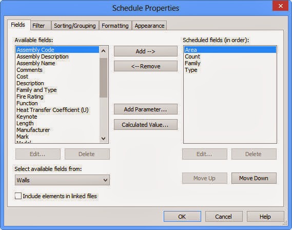
Schedule is basically a view. So, you can find this tool from the Create panel of the View tab; the New Schedule dialog box is displayed.

From this Category area, you can select any category to create schedule. Select the Wall from category and create Wall Schedule. Choose OK; the Schedule Properties dialog box is displayed. In this dialog box, select the Area, Count, Family, and Type and add them to the Schedule fields area using the Add button. You can add other fields also using the Add button. To arrange their order, you can use the Move Up and Move Down button.

                                     
You can use other tabs to set various settings or directly, choose OK to close the dialog box. After choosing the OK button.

You will see your schedule like this-


Friday, January 10, 2014

Design Options: An Introduction

  In this article, we are going to take you through what Design Options are, when would you use them.

The Design Options provides you with the flexibility of choosing several alternatives for your design. As a designer, you need to come up with multiple design ideas, so that you can select the best option that suits the functional, aesthetical, and economical requirement of your project. Therefore, you need to develop and evaluate several design options and then execute the best possible design option for your project.

The majority of your project will be fixed- this is what will constitute the “Main Model” with regards Design Options. All Revit elements that are designated as being in the Main Model will be common to all Options. This is a very important concept and one that you need to fully understand. If there are certain parts of your scheme that will vary (depending on which Option you are exploring), you need to move them out of the “Main Model” and into an “Option”.

Friday, January 3, 2014

Callout View

A callout view is used to display an enlarged view of a part of a building model. This view is important for detailing. Creating callout view is a common practice amongst engineers as it helps them to view the project more precisely and with a higher detail. In an architectural project, callout is used to show details of the basic building elements in a model. You can create callout in plan view or in elevation view. Note that, the callout tag added to these views will be linked to the callout view.

                                                                                                                   Callout Created

Callout Created Using Rectangle Tool

As you are aware callout view is used to give a detailed description about section of a model around which it is drawn. To create a rectangular callout view, invoke the Rectangle tool from the Callout drop-down in the Create panel; the Modify | Callout tab will be displayed. In the Properties Palette, the Type Selector drop-down list displays the type of callout view to be generated.

Callout Created Using Sketch Path Tool

In Autodesk Revit, you can create a customized callout view by using the draw tools. To do so, invoke the Sketch Path tool from the Create panel of the View tab; the Modify | Edit Profile tab will be displayed. In the Draw panel of this tab, the Line tool is selected by default. You can also select other sketching tools to create a callout of desired type. Next, choose the Finish Edit Mode button to exit the Modify | Edit Profile tab. In the Properties Palette, the Type Selector drop-down list displays the type of callout view to be generated.