Order E Book -Revit Structure

Learn Civil/GIS Software

CAD/CAM/CAE Software Services.

Trainings

Training Services.

BIM

BIM Services.

This is default featured slide 4 title

Go to Blogger edit html and find these sentences.Now replace these sentences with your own descriptions.

.

Friday, January 31, 2014

SCHEDULE

Schedule is a format for providing project information. Schedule primarily provide information in a tabulated form. Schedules are created by extracting information from a building model. In Autodesk Revit Architecture, all elements are parametric. This means that they have several properties associated with them. When you use these elements, the associated information is automatically added to the building model. This information can be then extracted for the creation of schedules.


Schedule is basically a view. So, you can find this tool from the Create panel of the View tab; the New Schedule dialog box is displayed.

From this Category area, you can select 
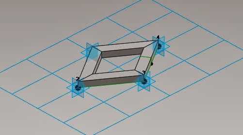
any category to create schedule. Select the Wall from category and create Wall Schedule. Choose OK; the Schedule Properties dialog box is displayed. In this dialog box, select the Area, Count, Family, and Type and add them to the Schedule fields area using the Add button. You can add other fields also using the Add button. To arrange their order, you can use the Move Up and Move Down button.

                                     
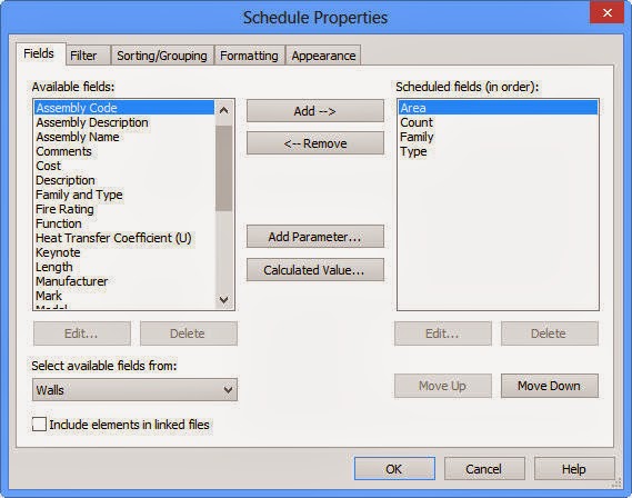
You can use other tabs to set various settings or directly, choose OK to close the dialog box. After choosing the OK button.

You will see your schedule like this-


Friday, January 10, 2014

Design Options: An Introduction

  In this article, we are going to take you through what Design Options are, when would you use them.

The Design Options provides you with the flexibility of choosing several alternatives for your design. As a designer, you need to come up with multiple design ideas, so that you can select the best option that suits the functional, aesthetical, and economical requirement of your project. Therefore, you need to develop and evaluate several design options and then execute the best possible design option for your project.

The majority of your project will be fixed- this is what will constitute the “Main Model” with regards Design Options. All Revit elements that are designated as being in the Main Model will be common to all Options. This is a very important concept and one that you need to fully understand. If there are certain parts of your scheme that will vary (depending on which Option you are exploring), you need to move them out of the “Main Model” and into an “Option”.

Friday, January 3, 2014

Callout View

A callout view is used to display an enlarged view of a part of a building model. This view is important for detailing. Creating callout view is a common practice amongst engineers as it helps them to view the project more precisely and with a higher detail. In an architectural project, callout is used to show details of the basic building elements in a model. You can create callout in plan view or in elevation view. Note that, the callout tag added to these views will be linked to the callout view.

                                                                                                                   Callout Created

Callout Created Using Rectangle Tool

As you are aware callout view is used to give a detailed description about section of a model around which it is drawn. To create a rectangular callout view, invoke the Rectangle tool from the Callout drop-down in the Create panel; the Modify | Callout tab will be displayed. In the Properties Palette, the Type Selector drop-down list displays the type of callout view to be generated.

Callout Created Using Sketch Path Tool

In Autodesk Revit, you can create a customized callout view by using the draw tools. To do so, invoke the Sketch Path tool from the Create panel of the View tab; the Modify | Edit Profile tab will be displayed. In the Draw panel of this tab, the Line tool is selected by default. You can also select other sketching tools to create a callout of desired type. Next, choose the Finish Edit Mode button to exit the Modify | Edit Profile tab. In the Properties Palette, the Type Selector drop-down list displays the type of callout view to be generated. 

Sunday, December 22, 2013

Revit-Series by CADCIM Technologies

Friday, December 20, 2013

Project Location- Vasari


When you create a project it is possible to specify the geographic location using the street address or the latitude and longitude. This is useful for generating location-specific shadows for views that use them, such as solar studies and walkthroughs. The location provides a basis for weather information, which is used during conceptual energy analysis.

To specify the project location, Analyze tab  > Project Location panel > Location. When your computer is connected to the Internet, and you have signed in to Autodesk online services, this dialog displays an interactive map through the Google Maps mapping service. To sign in see Autodesk Account.

Until you specify a different project location, the location is set to the longitude and latitude of the major city specified by Vasari for your locale.

For the Project Address, enter the street address, city and country. For Example-  Enter: Fulton Street & Pearl Street, Woodbridge Township, NJ 07095, USA


Click Import Site Image to import the Google map image of your location into your project file.


You can also access this dialog from the Sun Settings dialog, the Energy Settings dialog or in the drawing area, underneath the ViewCube, click the current location > Set Location.

Use the following tools to adjust the map as needed:
§  Pan. When you place the cursor over the map, the cursor changes to a hand, and you can drag the map to pan the view. For Zoom, Click + (Zoom in) or - (Zoom out), or drag the zoom slider to adjust the zoom level.
§  Map. Shows street map.
§  Satellite. Shows satellite imagery.
§  Terrain. Default view. Shows street map superimposed on topographical map.

Friday, December 13, 2013

Adaptive Components---Vasari


Wednesday, December 11, 2013

Curtain Panel Pattern Based- Autodesk Vasari


Vasari Introduction
Project Vasari is a standalone application that expands on the Revit conceptual mass family interface. Autodesk Project Vasari facilitates you with the curtain panel pattern based family. In this, you can create families of different shapes and patterns. Decorative panel can be obtained from the curtain panel pattern based family. These are project hosted elements. You can create panel and then it is to be loaded either on the adaptive component or in project environment.


Steps to Create Family and load it in Adaptive Component Family.

1.     Open the Curtain Panel Pattern Based Family from the Application Menu.


2.     The Rectangular curtain panel is displayed, by default.

3.     Choose the pattern and then change that pattern into rhomboid from the Type Selector drop-down list.

4.     The pattern is converted into rhomboid structure and change the Vertical spacing to 15’ in the Properties palette.


5.     Now, place a point on the pattern and set the work plane vertically on that point. 


6.     Accordingly, draw the rectangle on that workplane.


7.     Now, choose the drawn rectangle and the rhomboid pattern and then choose the Solid Form tool from the Create Form drop-down; the new pattern is formed.
           

8.     Now, load the project into the adaptive component family.

9.      After loading the family, draw any solid form and divide the surface.

10.   Now, select the complete element and select the family from the Properties palette.       

11.  The Family is loaded and the Curtain Panel Pattern based component is created.