Order E Book -Revit Structure

Learn Civil/GIS Software

CAD/CAM/CAE Software Services.

Trainings

Training Services.

BIM

BIM Services.

This is default featured slide 4 title

Go to Blogger edit html and find these sentences.Now replace these sentences with your own descriptions.

.

Monday, December 2, 2013

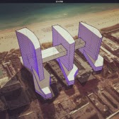
Autodesk Formit--------Conceptual Massing Tool


Autodesk Formit
Autodesk® FormIt mobile app helps you capture building design concepts digitally anytime, anywhere ideas strike. Use real-world site information to help create forms in context and support early design decisions with real building data. Experience a continuous Building Information Modeling (BIM) workflow by synchronizing designs in the cloud for further refinement using Autodesk® Revit® software products and other applications.
Express design ideas with easy-to-use tools:
  • Create forms quickly from a gallery of shapes
  • Directly manipulate forms using gestures for easy model changes
  • Save designs to the cloud and share with others
Easy access to site information:
  • Set project location in a searchable maps interface
  • Import satellite image of your site
  • Design directly in the context of your proposed building location
Make early design decisions:
  • Explore the effects of the sun using the location-aware Shadow Study tool
  • Start early program analysis by tracking gross building floor area ratio while you design
Experience a more continuous BIM workflow:
  • Store and share designs in the cloud using Autodesk® 360 cloud services
  • Easily transfer designs to desktop applications via RVT or SAT file formats
  • Explore design ideas and add detail to early design forms using award-winning BIM technology


Thursday, October 10, 2013

POINT CLOUD


Pretty Interesting new set of feature in Revit Architecture is, Point Cloud. Point Cloud is basically a collection of data in X,Y, and Z ordinates. You can collect this data by 3D scanners and then these 3D scanned point clouds will help you to create 3D models.

Point cloud files are .rcp and .rcs type format files. If the file is in raw format such as .pcg or .las format, then you will be prompted to index the data. The indexed point cloud file will then be converted into .rcp and .rcs format files which is further inserted in a Revit project. After inserting the point cloud file, you will use that file in the project. This file helps the user to provide a higher level of visual appearance of existing condition of a building. To view the existing building, capture it using laser scanners. Laser Scanners are used to sample point from the surface of the existing building and saves that data as point cloud. The data collected by the laser scanner is huge. Thus, Revit links a point cloud as a reference rather than embedding the complete file. Now, the existing building will be loaded in a project in the form of 3D scanned point cloud. Therefore, you can modify the existing building condition easily and the work performance will also be improved due to better visibility.

Friday, September 27, 2013

Stair Component into Custom Sketch form

Revit Architecture 2014 affords you with one of the exciting tool, i.e. convert Stair Component to Sketch. This feature aids you to convert the stair component to sketch and to design the stair component of your own style.

Figure 1: Creating a Stair Component
Let us know how we can create a stair component and then to convert it into the sketched form to edit and create your own stair. Here are the following steps to be followed to draw a stair component and then to convert them into sketch form.


1.       Open Revit Architecture 2014 session. The user interface screen will display.
2.       Now, invoke the Stair by Component tool from the Build panel of the Architecture tab, as shown in Figure 1; the Modify | Create Stair tab will be displayed.
3.       In the Modify|Create Stair tab, choose the Run tool and draw stair in the drawing area, as how in Figure 2.
4.       Now, create another run running parallel to it, Revit will automatically generate landing between the two runs, as shown in Figure 3.
5.       After creating complete stair, choose the Finish Edit Mode button from the Mode panel of the Modify|Create Stair tab.

6.       Now, choose the Default 3D view tool from the Quick Access Toolbar the 3D view of a stair will be displayed, as shown in Figure 4.
Figure 2: Converting Component into Sketch
1.       To convert a stair component to sketch, enter into the floor plan of your project.
2.       Select the stair component; the Modify | Stairs tab is displayed.
3.       Choose the Edit Stairs tool from the Edit panel of this tab, you will enter into the sketch form.
4.       Now, select the run which is to be modified and select the Convert tool, as shown in Figure 5. On doing so, the Stair- Convert to Custom window is displayed.

5.       Choose the Close button. Now, you are in custom sketch form.
6.       Choose the Edit Sketch tool from the Tools panel; the Modify|Create Stair > Sketch Run contextual tab is displayed.
7.       Now, from here you can modify the run by using the tools from the Draw panel of this tab.

You can read more detail of this topic on our latest text book Autodesk Revit Architecture 2014 for Architects and Designers

For more detail and know about our latest textbook log on to www.cadcim.com


Tuesday, April 23, 2013

Revit Structure 2014 and Robot Structural Analysis--------Link

Hi,
This is very exciting. This video will show how the bi-derictional associativity of Revit Structure works with Robot 2104.

New Book in Autodesk Revit Architecture 2014---- CADCIM Technologies


Schererville, IN

CADCIM Technologies®, a global leader in providing knowledge solutions to worlwide with engineering design and information technology requirements, announces its release of Autodesk Revit Architecture 2014 for Architects and Designers textbook

Book Description Publication Date:  May 25, 2013


Autodesk Revit Architecture 2014 for Architects and Designers textbook introduces the users to the spectacular realm of one of the most powerful software in the architectural quiver, Autodesk Revit Architecture. This textbook is a gateway to power, skill, and competence in the field of architectural and interior presentations, drawings, and documentations. This textbook is specially meant for professionals and students of architecture and interior design, facilities planners, and CAD professionals who are associated with the building construction and allied fields in the construction industry. Special emphasis has been laid to explain new concepts, procedures, and methods in Revit Architecture by using sufficient text and graphical examples. The accompanying tutorials and exercises, which relate to the real-world projects, help you understand the usage and capabilities of the tools available in Autodesk Revit Architecture.


This completely updated and revised edition of Autodesk Revit Architecture covers the features such as Autodesk 360 | Rendering, Revit Server, Conceptual Massing, Worksharing, Color Schemes, Shape Editing Tools for Slabs, Roofs and Floors, Interoperability with other software, Solar Studies, File linking have been explained in detail. Additionally, some other features such as Basic Building Components, Site Features, Massing, Annotations, Schedules, Cost Estimation, Rendering, and Walkthrough have also been explained. The text is supported by practical examples, tutorials, and exercises to clarify each concept. Written with the tutorial point of view and the learn-by-doing theme, the textbook is ideally suited for learning at your convenience and your pace.

Salient Features of the Textbook·  Consists of 16 chapters that are arranged in pedagogical sequence
·  Consists of 816 pages, hundreds of illustrations, and a comprehensive coverage of the concepts and tools of Revit Architecture 2014
·  Real-world projects and examples focusing on industry experience
·  Step-by-step examples that guide the users through the learning process
·  Includes changes and enhancements specific to Revit Architecture 2014
·  Effectively communicates the utility of Revit Architecture


Free Teaching and Learning Resources CADCIM Technologies provides the following free teaching and learning resources with this textbook:
·  Technical support
·  Customizable PowerPoint Presentations of every chapter (For faculty only)
·  Drawing files of all illustrations, examples, and exercises


Monday, April 22, 2013

Modifying Dimensions and Alternate Dimensions in Revit 2014


Dimension Enhancements in Revit 2014 
In Revit 2014, you can now insert alternate dimensions along with the main dimension. Figure 1 display dimensions with alternate units placed with it.  

Figure 1 Floor plan view displaying the alternate units along with the main unit

This feature  was one of the waited wish list fulfilled in Revit 2014. Architects and Designers throughout the globe can now communicate through the units they want.

To see how the alternate units can be set and can be used while documenting the model (BIM),  we will work on an illustration " Working on Alternate Units"

Illustration:  Essential Setups and Working on Alternate Units ( Time: 25 Minutes)

Opening  the File
First open the business_school.rvt file  or open a desired file of your choice. To download the business_school.rvt file login click on the link: http://www.cadcim.com/ProductDetails.aspx?ISBN=978-1-936646-29-6.

1. To open the file choose Open > Project from the Application Menu and select the appropriate file or the downloaded file.

2. Click on the First Floor Plan  level from the Project Browser, if you are using the  business_school.rvt file; the model will open in the selected view.


Changing the Detail Level
1. Next , to change the detail level of the drawing view, choose the Detail Level button form the View Control Bar; a flyout will be displayed as shown in Figure 2.

Figure 2  A flyout displayed on choosing the Detail Level button

2. From the displayed flyout choose the Fine option; the view will be displayed in fine detailing, as shown in Figure 3.
Figure 3  The view displayed in fine detailing

Setting up Dimensions and Using the Dimension Tool

1. Now, select the existing dimension from the drawing, the Modify Dimensions contextual tab will be displayed , as shown  in Figure 4.
Figure 4  The Modify |Dimension contextual tab displayed

2. In this tab, choose the Edit Witness Lines tool to change the witness line placement for the selected dimension;  the cursor will change and the witness line of the selected dimension is subjected to change as shown in Figure 5. 
Figure 5  The witness line is subject to change


3. Place the cursor on the grid D; the dimension changes and another dimension is also added. refer to Figure 6.


Figure 6  The dimension added on editing the witness line
4. Now, choose the Modify button from the Select panel to exit from the dimension.

Changing the Type Properties and Setting the Alternate Units
1. Now, select any of the exterior dimension; the Modify| Dimension tab will be displayed and the instance properties of the selected dimension will be displayed in the Properties Palette.  

2. In the Properties Palette choose the Edit Type button; the Type Properties dialog box will be displayed.

3. In this dialog box, choose the Duplicate button; the Name dialog box will be displayed.

4. In this dialog box enter Alternative Units in the Name edit box and choose the OK button; the Name dialog box will be closed and the Type Properties dialog box  will be displayed again.

5. In the Type Properties dialog box, scroll down and click in the Value field of the Alternate Units Parameter; a drop-down list will be displayed.

6.  From the drop-down list select the Right option.

From the drop-down list you can select the Left option if you desire to place the alternate units on the left side of the main dimension. :-)

7.  From the drop-down list select the Right option, refer to Figure 7.

 Figure 7  The various parameters of the Alternate units

8.  Now, choose the button corresponding to the Alternate Units Format value;  the Format dialog box will be displayed.

9. In this dialog box, select the Meters option from the Units drop-down list and m from the Unit symbol drop-down list, respectively.

10.Now, choose the OK button; the Format dialog box will close.

11. Now in the Alternate Unit Prefix and Alternate Unit Suffix parameters enter" (" and" )" characters, respectively.

12. Now. choose the OK button; the Type Properties dialog box will be closed and the new type is created and applied in the selected dimension as shown in Figure 8.

 Figure 8   Alternate dimensions displayed


Saturday, April 20, 2013

Press -Realease- AutoCAD MEP 2014


AutoCAD MEP 2014 for Designers by Prof. Sham TIckoo and CADCIM Technologies. To be released on 20 th May 2013. (Available in e-book also ) For information log on to www. cadcim.com or mail us @ sales @cadcim.com ; (219) 228-4908