


Sunday, December 22, 2013
Friday, December 20, 2013
Project Location- Vasari
When you
create a project it is possible to specify the geographic location using the
street address or the latitude and longitude. This is useful for generating
location-specific shadows for views that use them, such as solar studies and
walkthroughs. The location provides a basis for weather information, which is
used during conceptual energy analysis.
To
specify the project location, Analyze tab > Project Location panel > Location.
When your computer is connected to the Internet, and you have signed in to
Autodesk online services, this dialog displays an interactive map through the
Google Maps mapping service. To sign in see Autodesk
Account.
Until you specify a different project
location, the location is set to the longitude and latitude of the major city
specified by Vasari for your locale.
For the
Project Address, enter the street address, city and country. For Example- Enter: Fulton Street & Pearl Street,
Woodbridge Township, NJ 07095, USA

Click Import Site Image to import the Google map image of your
location into your project file.
You can also access this dialog from the Sun Settings dialog, the
Energy Settings dialog or in the drawing area, underneath the ViewCube, click
the current location > Set Location.
Use the following tools to adjust the map as needed:
§
Pan. When you place the cursor over the map, the cursor changes to
a hand, and you can drag the map to pan the view. For Zoom, Click + (Zoom
in) or - (Zoom out), or drag the zoom slider to adjust the
zoom level.
§
Map. Shows street map.
§
Satellite. Shows satellite imagery.
§
Terrain. Default view. Shows street map superimposed on
topographical map.
Friday, December 13, 2013
Wednesday, December 11, 2013
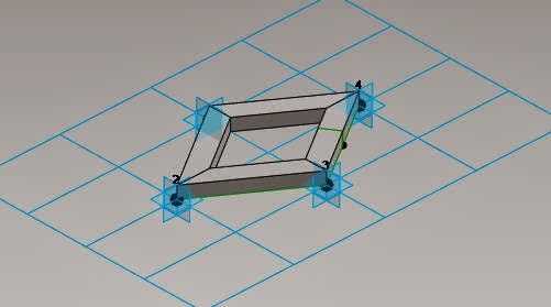
Curtain Panel Pattern Based- Autodesk Vasari
Vasari Introduction
Project Vasari is a standalone application that expands on the Revit conceptual mass family interface. Autodesk Project Vasari facilitates you with the curtain panel pattern based family. In this, you can create families of different shapes and patterns. Decorative panel can be obtained from the curtain panel pattern based family. These are project hosted elements. You can create panel and then it is to be loaded either on the adaptive component or in project environment.
Project Vasari is a standalone application that expands on the Revit conceptual mass family interface. Autodesk Project Vasari facilitates you with the curtain panel pattern based family. In this, you can create families of different shapes and patterns. Decorative panel can be obtained from the curtain panel pattern based family. These are project hosted elements. You can create panel and then it is to be loaded either on the adaptive component or in project environment.
Steps to Create Family and load it in Adaptive
Component Family.
1. Open
the Curtain Panel Pattern Based Family from the Application Menu.

2. The
Rectangular curtain panel is displayed, by default.
3. Choose
the pattern and then change that pattern into rhomboid from the Type Selector
drop-down list.
4. The
pattern is converted into rhomboid structure and change the Vertical spacing to
15’ in the Properties palette.

5. Now,
place a point on the pattern and set the work plane vertically on that point.

6. Accordingly,
draw the rectangle on that workplane.
7. Now,
choose the drawn rectangle and the rhomboid pattern and then choose the Solid
Form tool from the Create Form drop-down; the new pattern is formed.

8. Now,
load the project into the adaptive component family.
9. After loading the family, draw any solid form
and divide the surface.
10. Now,
select the complete element and select the family from the Properties palette.
11. The Family is loaded and the Curtain Panel
Pattern based component is created.

Barriers to Building Information Modeling
Barriers to BIM
The ultimate objective is to build an integrated BIM—a virtual building before we make expensive mistakes with concrete, glass and steel. But tradition, contractual separation, archaic laws, technical limitations, interoperability problems and culture hinder us.
Software and hardware constraints: A BIM model theoretically has unlimited ability to hold information. But any practical project model will fall short of what is theoretically possible. Despite faster and faster computers and more efficient software, the model slows down as it enlarges.
Cost practicalities: At some point, it becomes impractical to add detail to the model. We still assume the builder will use some judgment in the field. A drawing doesn’t need to show all the nail locations in a wood frame.
Universal adaption: The fruition of BIM will depend on widespread use by designers, contractors and manufacturers. But until trade contractors and manufacturers are operational with BIM, we will limp along with incomplete integration.
Interoperability: Any CM or PM that has managed a program that included multiple architects and multiple CMs has faced the frustrating problems of interoperability in trying to integrate data from different project management information systems. It is hard to share data between Autodesk’s Constructware, e-Builder and Meridian’s Prolog. The same problem exists with BIM software.
A fully integrated BIM model is a vision, not a reality. At current levels of development, architects engineers, consultants, builders and fabricators may have independent BIM models, legacy CAD systems and legacy paper systems. Those who use BIM software may not use the same programs
The ultimate objective is to build an integrated BIM—a virtual building before we make expensive mistakes with concrete, glass and steel. But tradition, contractual separation, archaic laws, technical limitations, interoperability problems and culture hinder us.
Cost practicalities: At some point, it becomes impractical to add detail to the model. We still assume the builder will use some judgment in the field. A drawing doesn’t need to show all the nail locations in a wood frame.
Universal adaption: The fruition of BIM will depend on widespread use by designers, contractors and manufacturers. But until trade contractors and manufacturers are operational with BIM, we will limp along with incomplete integration.
Interoperability: Any CM or PM that has managed a program that included multiple architects and multiple CMs has faced the frustrating problems of interoperability in trying to integrate data from different project management information systems. It is hard to share data between Autodesk’s Constructware, e-Builder and Meridian’s Prolog. The same problem exists with BIM software.
A fully integrated BIM model is a vision, not a reality. At current levels of development, architects engineers, consultants, builders and fabricators may have independent BIM models, legacy CAD systems and legacy paper systems. Those who use BIM software may not use the same programs
BIM Model Management
Managing a BIM Model
Managing a Building Information
Model is similar to managing an actual model in site. A construction manager must understand the
technology of construction. But the more crucial job is orchestrating the work
of hundreds of organizations—coordinating the assembly of materials on-site
with decision-making, sequencing, and supply chain management.
Most of a project is built off-site. If the
on-site management team doesn’t manage the off-site activities there will be delays.
Managing the interrelationships is as important as understanding the technology
of the work. In the simplest sense, it doesn’t do any good for a construction
superintendent to know about forming and finishing concrete if the concrete
truck isn’t scheduled for delivery at the right time.
A BIM model has similar
requirements. Managing the development of a virtual construction model requires
skills that are similar to managing the real thing. Too often BIM production is
staffed with people who understand BIM technology but don’t understand how to
manage the workflow from multiple sources.
The management job requires
setting BIM standards, understanding constructibility and construction
sequence, evaluating supply chain data and vetting information that is
submitted to be input into the model. But most of all, it requires
understanding how to suck this information from multiple sources into an
integrated model. The manager must have clout in the organization to get the
attention of the extended IPD team to schedule information flow, analysis and
problem solving. And since inputs to a BIM model may ricochet through the
model, the manager must review and evaluate the accuracy of inputs—just as a
CFO ensures that there are procedures to evaluate the inputs of financial
information before they are posted to a general ledger.
A BIM model manager requires the
support of the IPD management committee who must set policies to adopt the
technology, buy and install the software for members who do not have it, train
the team, champion the use. Finally, they will need to establish workflows for
a BIM process that may be developed by the BIM model manager.
An IPD team needs a BIM manager
and an interdisciplinary BIM team staffed with people from member firms. The
BIM team integrates drawings from the AEs, subs and manufacturers. They develop
4D and 5D models. They detect coordination problems with clash detection
routines. Constructibility reviews trigger design adjustments—made with the
collaboration of the AEs. RFIs are anticipated and if collaboration ongoing,
should be minimal. In developing the model, questions surface before
construction.
The BIM model manager must be a
person with good interpersonal skills to build the collaborative culture
required to produce an integrated BIM model. The manager must build trust and
networks of personal communication within the contracting team. As with real
construction, the more personal contact and the more trust, the more
collaboration. BIM allows trust to be built early, well before construction
begins. There’s an opportunity to allocate model space to each subcontractor to
give them confidence that the process will not only find clashes in their
systems before they get to the field, but that the sub will have the ability to
model the clearances and working space needed to install their work.
Architects have typically been
the primary source of BIM models, fulfilling their traditional role in
developing the drawings and specifications that document the product—the
description of the design, the intended physical result.
CMs have usually taken the lead
in providing project management information (PMIS) systems—gathering and
integrating data from the extended project team. These systems have
concentrated on process—tracking contractual matters such as cost, schedule and
quality control; RFIs and change orders.
But now CMs are developing
in-house BIM teams and are developing BIM models prior to construction.2
Eventually, it is likely that an
IPD Core Team will build integrated groups to produce integrated documents.
Clearly, managing virtual construction will require technical knowledge of both
process and product. Virtual construction will require AEs with product
expertise and CMs with process expertise.
BIM in Industry
BIM Characteristics
A BIM model is a digital description of a project. It may
include information such as the physical configuration, programmatic
requirements, functional characteristics, specifications, systems performance,
supply chain threads, construction sequence, cost or any other information that
might be useful.
Plug-ins:
Specialized software may be “plugged in”
with algorithms that can adjust related building systems if there is a design
change. These “plug ins” can include programs for structural and mechanical
design. For instance, if a room is enlarged, the size of the structural members
can be automatically recalculated and resized. The model adjusts itself. If the
building is rotated on the site, the heat gain and loss may be recalculated.
Other plug-ins may focus on energy analysis, LEED certification, cost
estimating or construction scheduling.
Reports:
BIM ideologues will
quickly tell you that BIM is not drafting software. It is a database. Drawings
are simply one form of report. Like any digital database, a BIM model can
produce reports—subsets of information for special purposes. These reports can
be in the form of 2D or 3D drawings or an infinite variety of custom
alphanumeric reports. The IPD team can tailor reports for specific purposes
instead of grappling with a large set of 30” x 40” construction drawings and a
fat set of specifications that obscures required information.
For instance, architects can produce a report in 3D and in
color, rendered for comprehension by non-technical people. They can deliver
drawings for review by entitlement agencies (building permits, accessibility
requirements, environmental concerns, aesthetic compatibility or whatever) that
address the agency’s specific requirements. Assembly details can be produced on
site for current construction challenges. Facility managers may access
life-cycle, maintenance and replacement information.
4D and 5D models:
BIM can have sequence and construction
duration information attached to drawing elements that represent the building
systems (4D modeling). A computer program can animate construction progression.
A user can input a date to observe current state of completion. The builder can
analyze on-site material staging problems, develop phasing plans, improve the
sequencing of trade contractors or analyze the cost of construction delays.
Cost can also be attached to drawing elements that represent building systems (5D
modeling) for estimating and value engineering. The estimate can progress in
lockstep with design.
Clash Detection:
At the simplest level, pasting shop drawings into a CAD
drawing quickly indicates a misalignment or a poor fit. Even in a 2D model, it
is obvious if a window doesn’t fit between a pair of columns. However, problems
are not always that obvious in 2D models. Conflicts are often caused when a
building system designed by one consultant interferes with a system designed by
another
consultant on separate drawings. For instance, if a lighting
consultant locates recessed light fixtures on an architectural reflected
ceiling plan without checking beam locations on structural drawings, the
recessed can may poke into a beam. And we have all experienced a mechanical
engineer plotting duct runs that pass through the structural engineers’ beams.
BIM software provides sophisticated “clash detection” routines that indicate
when two systems or products occupy the same space.
Direct fabrication control:
Traditionally, fabricators
develop shop drawings based on their interpretation of the plans and
specifications. They are checked by the AE. Errors occur at each translation.
By pasting shop drawings directly into the BIM model, errors and conflicts are
more apt to be detected. Ultimately, a BIM model may include algorithms for
CNC.
Facilities
Management:
An integrated BIM
model is a good bit more valuable to facility managers than typical “as built”
drawings. It may contain warranty data, spare parts lists and sources, useful
life expectations and maintenance recommendations. It may contain original
layouts as well as remodeling and renovation documentation. direct fabrication
of building systems, such as ductwork, curtain wall, millwork. While there are
still opportunities for error in these automated processes, they are reduced
and often eliminated. Precision is increased and supply chain workflow is
shortened.
BIM as a contract
tool:
Although IPD may minimize the contractual silos between the
members, it is unlikely that an IPD team will include 50 to 75 subcontractors.
Contractual separation will remain for most of the design and construction
team. Multiple customized reports from a BIM model will assume important roles
as contractual tools. The tools will work both ways—clarifying agreements with
both the owner and with subcontractors.
The initial agreement with the owner will likely be a
written document, perhaps with some simple diagrams to describe the intended
result. As the project progresses, printed reports from the BIM can then
augment that original agreement, defining the work for staged approvals just as
traditional SD, DD or CD documents have done. However, rendered 3D reports from
the model will do a better job of ensuring a meeting of the minds with the
owner or users who may lack experience with technical Construction Documents.
Computer Numerical Control refers to computer instructions
that drive machine tools used to fabricate components. The technology is labor
efficient, accurate, repeatable and facilitates complex forms.
The BIM will then become the framework for describing the
work to subcontractors. As the design develops, subs will be asked to propose
or bid on aspects of the work. When selected, aspects of their technical
proposal may become part of the BIM—to be augmented or replaced with shop
drawings as their work is developed.
Subscribe to:
Posts (Atom)


